
EV battery busbar failure can cause overheating, voltage loss, insulation damage, and vehicle downtime. The main risk areas are busbar corrosion, electrical resistance, and vibration fatigue. For battery pack manufacturers and overseas distributors, the best prevention plan combines correct material selection, controlled assembly, thermal testing, and regular inspection.
A busbar is a conductive part that connects battery cells, modules, contactors, fuses, and the battery management system. It carries high current through a small space. When a joint becomes loose, contaminated, cracked, or too hot, resistance increases and the heat can damage nearby components.
This guide explains the most common EV battery busbar failure modes, their root causes, warning signs, and practical solutions. It also provides a simple inspection flow that can be used during design, production, and field service.
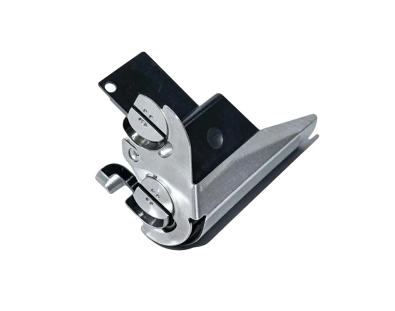
1. Loose Busbar Bolts and High Contact Resistance
A loose bolt reduces the contact area between the busbar and the terminal. The current then passes through a smaller path. This creates higher contact resistance and local heat. The heat can loosen the joint even more, creating a self-reinforcing failure cycle.
Common causes include incorrect torque, poor torque tools, repeated thermal expansion, surface contamination, and the use of unsuitable washers. Manual tightening without a controlled process is a major risk in high-volume battery pack production.
Why this failure happens
Typical signs include a darkened terminal, melted insulation, a hot spot during an infrared scan, unstable pack voltage, and a local temperature that is much higher than nearby joints. A voltage drop test can also identify a high-resistance connection under load.
Warning signs
Define a torque range for every busbar joint and record the result during assembly. Use calibrated electric or digital torque tools. Keep contact surfaces clean and flat. Where suitable, use a locking washer, thread-locking method, or engineered fastening system that matches the battery pack design.
How to prevent it
2. Busbar Corrosion and Surface Contamination
Copper and aluminum busbars can corrode when moisture, salt, chemicals, or condensation reach the metal surface. Corrosion creates an oxide layer that reduces conductivity. It can also weaken the joint and cause uneven current flow.
Corrosion risk increases in electric buses, commercial vehicles, marine vehicles, and vehicles used in coastal or high-humidity areas. Battery packs with poor sealing, blocked vents, or damaged gaskets are more likely to develop this problem.
Why this failure happens
Select a suitable surface finish, such as nickel plating, tin plating, or another proven coating. The correct finish depends on the base metal, terminal material, working temperature, current level, and environment. Do not mix metals without checking galvanic corrosion risk.
Control the production environment. Prevent oil, dust, fingerprints, and cleaning chemicals from reaching contact areas. Use sealed battery housings, suitable gaskets, drainage paths, and humidity testing. Onlink can support busbar designs with plated surfaces and insulation options for different pack environments.
How to prevent it
3. Busbar Cracks Caused by Vibration and Mechanical Stress
An EV battery pack is exposed to road shock, vibration, sudden acceleration, braking, and repeated temperature changes. A rigid busbar can transfer this stress directly to the cell terminal. Over time, the busbar or terminal may develop a small crack.
Cracks often start at sharp corners, punched holes, narrow sections, weld points, or areas with poor bend control. A busbar that is forced into position during assembly may already have hidden stress before the vehicle begins operation.
Root causes
Use rounded corners, suitable bend radii, and controlled forming tools. Avoid placing holes too close to edges. Add flexible sections where the battery structure allows movement. Make sure the busbar is aligned naturally and does not need force during installation.
Validate the design with vibration testing, mechanical shock testing, and thermal cycling. Inspect critical welds and bends with visual checks, resistance checks, and non-destructive methods when required.
Prevention methods
4. Busbar Overheating and Current Overload
Busbar heat is mainly related to current, resistance, and the ability to remove heat. In simple terms, heat increases quickly as current rises because electrical loss follows the I2R relationship. A small increase in resistance can create a large temperature rise at high current.
Overheating can result from an undersized cross section, too much current, poor airflow, a high-resistance joint, blocked cooling channels, or an incorrect thermal design. Repeated fast charging can expose a weak design sooner than normal driving.
Why temperature rises
Calculate the continuous current, peak current, duty cycle, ambient temperature, and allowable temperature rise. Select the busbar width and thickness based on real operating conditions, not only a short laboratory current value. Consider copper busbar and aluminum busbar options based on conductivity, weight, cost, and corrosion behavior.
Use thermal simulation during the design stage. Confirm the result with a full-load test. Measure temperature at the center of the busbar, at joints, near welds, and around insulation. A stable design should keep the hottest point within the material and pack limits during the complete test cycle.
How to prevent overheating
5. Insulation Damage and Short Circuit Risk
An exposed busbar can short against another conductor, the battery case, a module frame, or a tool. Insulation may be damaged by sharp edges, incorrect clearance, heat, vibration, assembly pressure, or contact with a metal cover.
A short circuit can create an arc, fuse a conductor, damage cells, or trigger a serious battery safety event. Insulation failure is especially dangerous because the defect may not be visible during a basic visual inspection.
Common insulation failures
Use an insulating film, molded cover, heat-shrink tube, powder coating, or laminated busbar structure when appropriate. Control creepage distance and clearance according to the pack voltage and environmental conditions. Protect sharp edges with rounded designs or edge guards.
Perform insulation resistance and dielectric withstand tests. Check the complete assembly, not only the individual busbar. Confirm that covers remain secure after vibration and thermal cycling. A good design should prevent contact even if one clip or fastener becomes loose.
Prevention methods
6. Welded Joint Cracks and Poor Cell Connections
Many battery packs use laser welding, ultrasonic welding, or resistance welding to join busbars to cell terminals. Incorrect energy, pressure, alignment, or surface preparation can create a weak weld. A weld may look acceptable while having low mechanical strength or high electrical resistance.
Poor welding can be caused by dirty surfaces, incorrect material combinations, electrode wear, unstable power, excessive heat, or poor fixture control. Repeated expansion and contraction can then open a small weld defect.
Failure mechanism
Set welding parameters through a documented process window. Monitor power, time, pressure, displacement, and tool condition. Use sample pull tests, cross-section checks, resistance tests, and visual inspection. For high-volume production, automated monitoring can identify process drift before many parts are affected.
Design the joint so that current and mechanical load are distributed across a suitable area. Avoid placing a weld in a high-stress bend. Onlink busbar solutions can be adapted for welding, bolting, or hybrid connection structures.
Quality controls
7. Incorrect Material, Size, or Plating Selection
| Material or design | Main benefit | Main risk | Typical control |
|---|---|---|---|
| Copper busbar | High conductivity and strong electrical performance | Higher weight and material cost | Use suitable plating and mechanical support |
| Aluminum busbar | Lower weight and good cost efficiency | Oxide layer and joint compatibility issues | Control surface treatment and joint design |
| Laminated busbar | Compact layout and controlled insulation | Higher design and manufacturing complexity | Check dielectric strength and layer bonding |
| Flexible busbar | Better tolerance for movement and vibration | Possible fatigue if badly formed | Control bend radius and fatigue testing |
A busbar can fail even when its material is conductive enough. The complete design must match the current, voltage, temperature, vibration, space, assembly method, and service environment. Plating must also be compatible with the terminal and welding process.
Material comparison
| Failure mode | Most common cause | Early warning sign | Best prevention |
|---|---|---|---|
| Loose connection | Incorrect torque or thermal cycling | Local hot spot or voltage drop | Controlled torque and joint inspection |
| Corrosion | Moisture, salt, or mixed metals | Oxide, discoloration, rising resistance | Sealing, plating, and humidity testing |
| Vibration crack | Rigid design or sharp corner | Intermittent voltage or visible crack | Flexible design and vibration validation |
| Overheating | Small cross section or poor cooling | High temperature during load | Current calculation and thermal testing |
| Insulation breakdown | Abrasion, heat, or low clearance | Low insulation resistance | Protective covers and dielectric tests |
| Weld failure | Wrong energy, pressure, or alignment | Weak pull strength or unstable resistance | Weld process monitoring and sample tests |
Busbar Failure Mode Comparison
Use the following process before releasing a new busbar design or changing a production supplier.
- Step 1: Define the working voltage, continuous current, peak current, temperature range, vibration level, and expected service life.
- Step 2: Select the material, thickness, width, surface finish, insulation method, and connection type.
- Step 3: Check electrical resistance, current capacity, temperature rise, clearance, creepage, and mechanical stress.
- Step 4: Build samples using the same forming, plating, welding, and fastening methods planned for mass production.
- Step 5: Test the samples under full load, fast charge, thermal cycling, humidity, vibration, shock, and insulation conditions.
- Step 6: Inspect joints with torque records, resistance measurements, thermal imaging, weld checks, and visual inspection.
- Step 7: Release the design only after test data meets the approved limits. Record all material and process changes.
- Step 8: Monitor production with incoming inspection, process checks, final electrical tests, and periodic reliability audits.
Flow: Define load and environment, select material, design the joint, build samples, test under stress, inspect failure risks, approve the design, monitor production.
Step-by-Step EV Battery Busbar Prevention Process
Before purchasing EV battery busbars, ask the supplier for clear technical information. The supplier should provide material grade, dimensions, tolerance, surface treatment, insulation details, connection method, and applicable test results.
- Confirm the busbar current rating for both continuous and peak operation.
- Check whether the material is copper, aluminum, or a hybrid structure.
- Review plating thickness and surface finish requirements.
- Ask how torque, welding, bending, and insulation quality are controlled.
- Confirm the design has passed thermal cycling and vibration testing.
- Check packaging protection against moisture, dust, and deformation.
- Request lot traceability for raw material and production inspection.
- Verify that samples match the approved drawing and performance data.
Inspection Checklist for Overseas Buyers and Distributors
How Onlink Helps Reduce EV Battery Busbar Risk
Onlink supports EV battery pack component projects with busbar design, material selection, insulation solutions, and production control. The correct solution may be a copper busbar, aluminum busbar, laminated busbar, flexible busbar, or a custom connection part.
A reliable project begins with accurate application data. Share the battery voltage, current, cell format, terminal type, installation space, cooling method, connection process, and target production volume. This information helps the engineering team reduce resistance, control heat, improve insulation, and prevent mechanical stress.
For overseas buyers and distributors, supplier communication is also part of failure prevention. Use approved drawings, inspection standards, sample records, and change-control documents. This reduces the risk that a small material or process change will create a large field problem.
Key Takeaway
The most common EV battery busbar failures are loose joints, corrosion, vibration cracks, overheating, insulation damage, weld defects, and incorrect material selection. Most can be prevented before mass production through correct sizing, controlled assembly, suitable plating, reliable insulation, and testing under real operating conditions.
Do not judge a busbar only by its appearance or short-term conductivity. Check the complete system: current, heat, vibration, moisture, insulation, fastening, welding, and service life. A busbar that passes these checks gives the battery pack better safety, lower maintenance cost, and more stable long-term performance.


