Aug.31,2026
For battery engineers, electric vehicle integrators, and purchasing teams comparing an EV battery busbar design guide, the difficult part is not drawing a copper strip—it is proving that the part will carry the required load without excessive heating, voltage drop, vibration fatigue, or insulation failure. This article explains lithium-ion battery busbar current capacity calculation, copper vs aluminum EV busbar selection, laminated busbar construction, battery management system connections, thermal management, ampacity, continuous current, and contact resistance. The practical method is suitable for cylindrical, prismatic, and pouch-cell packs, including high-voltage traction batteries developed with an experienced EV Battery Pack Components Manufacturer such as Onlink.
A busbar is a low-impedance conductor that connects cells, modules, contactors, fuses, current sensors, and external power terminals. In a traction battery, it must survive more than the nominal pack current. Regenerative braking, acceleration peaks, pre-charge events, charger operation, short-circuit energy, and repeated thermal cycles all influence the design.
For example, a 400 V battery delivering 80 kW requires approximately:
I = P ÷ V = 80,000 W ÷ 400 V = 200 A
If the same pack reaches 120 kW during a short acceleration event at 360 V, current rises to approximately 333 A. Designing only for the 200 A average value can create a busbar that passes a static bench test but overheats during real driving.
The first design task is therefore to define:
A busbar that carries 300 A for two seconds may require a different cross-section from one carrying 300 A continuously. The thermal time constant of the assembly, not only the conductor area, determines whether a short overload is acceptable.
Ampacity is the maximum current a conductor can carry under specified thermal conditions. It is not a universal material property. The same 5 mm × 1 mm copper strip can have different ampacity when it is exposed to free air, clamped between dielectric layers, mounted against a cold aluminum plate, or surrounded by a sealed battery enclosure.
Continuous current is the load that can be maintained without exceeding the defined temperature limit. Peak current is time-dependent and must be evaluated using transient thermal analysis or physical testing.
For a straight conductor, resistance is calculated as:
R = ρL ÷ A
where ρ is resistivity, L is conductor length, and A is cross-sectional area. Copper has a resistivity of approximately 1.68 × 10⁻⁸ Ω·m at 20°C, while common electrical aluminum is approximately 2.82 × 10⁻⁸ Ω·m at 20°C. Aluminum therefore needs roughly 1.68 times the cross-sectional area of copper to achieve similar resistance at the same temperature.
Connection points introduce additional losses. Contact resistance can result from oxide films, insufficient clamping force, plating damage, burrs, contamination, or thermal expansion. At 300 A, an additional 100 micro-ohms creates:
P = I²R = 300² × 0.0001 = 9 W
That 9 W may be concentrated in a small joint rather than distributed across the complete busbar, creating a localized hot spot.
High-current DC busbars also have parasitic inductance. During contactor switching or a short-circuit interruption, the voltage generated by inductance is approximately:
V = L × di/dt
A laminated positive-and-negative busbar arrangement reduces loop area and can lower inductive voltage overshoot. However, insulation spacing must still satisfy the applicable vehicle, battery, and high-voltage safety requirements. Creepage is the surface distance between conductive parts, while clearance is the shortest distance through air.
At pack voltages above 400 V, contamination, condensation, and altitude can reduce insulation margin. A design that passes a clean laboratory test may fail after humidity, dust, and vibration exposure unless the creepage path and sealing strategy are properly controlled.
Begin with the worst operating voltage rather than the nominal voltage:
I = P ÷ Vmin
For a 100 kW inverter operating at a minimum battery voltage of 320 V:
I = 100,000 ÷ 320 = 312.5 A
Add the required engineering margin. A 20% current margin produces a design current of approximately 375 A. The exact margin depends on the control strategy, protection system, validation data, and customer requirements.
Cross-sectional area is:
A = width × thickness
A copper busbar measuring 20 mm wide and 2 mm thick has an area of 40 mm². A 30 mm wide and 2 mm thick bar has an area of 60 mm². Increasing width often improves heat dissipation more effectively than increasing thickness because the exposed surface area grows while the forming load may remain manageable.
There is no single safe current-per-square-millimeter rule for every EV pack. As a preliminary starting point, an enclosed copper busbar may be evaluated in the range of approximately 2 to 5 A/mm², while a short-duration pulse design may tolerate a higher value if transient testing confirms the temperature rise. These values are screening estimates, not final certification limits.
Assume a 0.8 m copper busbar with a 40 mm² cross-section. At 20°C:
R = 1.68 × 10-8 × 0.8 ÷ 40 × 10-6 = 0.000336 Ω
At 300 A:
Voltage drop = I × R = 300 × 0.000336 = 0.101 V
Power loss = I² × R = 300² × 0.000336 = 30.24 W
A 101 mV drop may be acceptable in some power paths but excessive in a precision sensing or low-voltage auxiliary circuit. For the complete pack, calculate every busbar segment, fastener interface, fuse connection, shunt, and contactor terminal.
Copper resistance increases with temperature. A commonly used approximation is:
RT = R20[1 + α(T − 20)]
For copper, α is approximately 0.00393/°C. If the conductor reaches 100°C, its resistance is approximately 31% higher than at 20°C. The 30.24 W loss in the previous example can therefore increase to roughly 39.6 W before considering changes in heat transfer.
This feedback loop matters: higher current creates heat, higher temperature increases resistance, and increased resistance creates additional heat. Thermal simulation and temperature measurement should be used to confirm that the design remains stable.
Bolted joints should be evaluated for torque retention, washer selection, surface flatness, plating compatibility, and thermal expansion. A busbar with low bulk resistance can still fail because its joint resistance increases after vibration or corrosion.
For production, specify torque range, tightening sequence, fastener grade, washer geometry, contact plating, and inspection method. Micro-ohm resistance testing before and after vibration and thermal cycling can identify weak interfaces.
Copper provides lower electrical resistivity, compact dimensions, strong terminal performance, and relatively straightforward joining. It is often selected for:
Common copper grades for busbars include C11000 and equivalent high-conductivity copper grades. Annealed copper bends easily, while harder tempers provide greater resistance to deformation. The selected temper must match the forming radius and vibration requirement.
Aluminum has a density of approximately 2.70 g/cm³, compared with approximately 8.96 g/cm³ for copper. Even after increasing the aluminum cross-section to compensate for its higher resistivity, a properly designed aluminum busbar can reduce conductor mass significantly.
Aluminum is attractive for long pack interconnects, large cross-section power rails, and applications where weight reduction is more important than minimum volume. The design must address:
An aluminum busbar should not simply replace a copper bar with the same dimensions. At a minimum, compare resistance, temperature rise, mass, bend radius, terminal pressure, corrosion behavior, and manufacturability.
Tin plating is commonly used to improve solderability and provide a stable contact surface. Nickel plating can offer stronger wear and temperature performance, although its electrical interface behavior and cost must be considered. Silver plating provides excellent conductivity but may be selected only where its cost and tarnish behavior are justified.
Plating thickness should be specified with a tolerance, not only a nominal value. Masking requirements, edge coverage, post-forming cracks, and exposed base metal should be included in the supplier quality plan.
Stamped copper busbars are suitable for high-volume production with repeated geometry. Machined busbars support prototypes and low-volume designs but can create higher material waste. Laminated busbars combine conductive layers with dielectric insulation and provide controlled spacing, lower loop inductance, and simpler assembly.
Flexible busbars use thin layered conductors, often joined by ultrasonic welding or laser welding. They can absorb cell-to-cell dimensional variation and reduce stress transferred to battery terminals. Their current capacity depends on the total copper foil area, weld design, insulation system, and cooling path.
A sudden width reduction increases current density. Sharp internal corners increase stress concentration and may reduce fatigue life under vibration. Rounded corners, controlled bend radii, and strain-relief features improve durability.
Keep high-current conductors away from temperature-sensitive cell vents, polymer housings, and low-voltage signal harnesses. Where the busbar passes near a grounded enclosure, use a defined insulation barrier rather than relying on air distance alone.
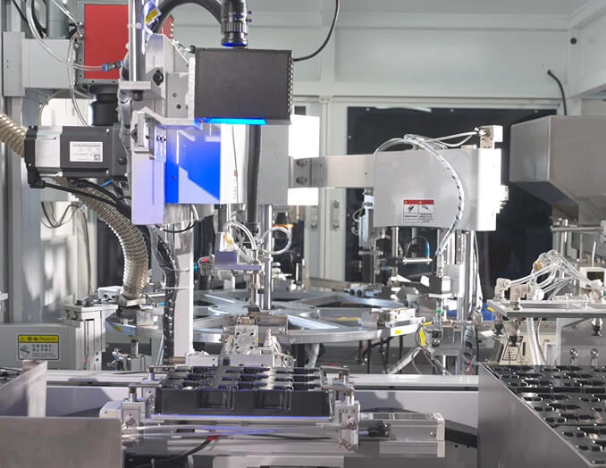
The image below illustrates the type of busbar and battery interconnect arrangement that can be reviewed during a design discussion with Onlink:
Use a spreadsheet, circuit model, or electrical simulation tool to calculate resistance, voltage drop, current distribution, and power loss. Include parallel paths, weld interfaces, fuse links, shunts, contactors, and connector terminals.
For a parallel busbar arrangement, confirm that each path has similar resistance. A 10% resistance mismatch can produce an unequal current split, especially when the conductors operate at different temperatures.
Estimate conduction, convection, and radiation. In a sealed pack, natural convection may contribute less than expected, while conduction into a cooling plate or enclosure may dominate. Include the thermal resistance of insulation films and mounting clips.
For a first physical test, place thermocouples at the busbar center, narrowest section, terminal interface, weld area, and nearest cell surface. Use infrared imaging only after correcting for surface emissivity; polished copper can produce misleading readings.
Run the defined continuous current until thermal equilibrium, then apply the peak-current profile that represents acceleration and regenerative braking. Record current, voltage at both ends, temperature at each hot spot, and ambient conditions.
A practical acceptance record should show that the measured temperature remains below the limit after the complete duty cycle, not merely during the first few minutes. Also compare measured voltage drop with the calculated value. A significant difference often indicates contact resistance or an incorrect effective length.
Subject the busbar assembly to vibration, mechanical shock, thermal cycling, humidity, salt exposure where applicable, and coolant contamination testing. After testing, inspect for:
Perform insulation-resistance, dielectric withstand, and isolation monitoring checks according to the applicable vehicle and battery safety requirements. Validate the worst-case tolerance stack-up, including connector movement, busbar misalignment, insulation compression, and enclosure deformation.
A good prototype can still become an unreliable production part if the design depends on manual alignment. Add datums, poka-yoke features, controlled locating holes, and visual inspection points. Define burr limits because a sharp burr can pierce insulation or create a partial discharge site.
For laser welding, control beam alignment, energy input, weld penetration, surface cleanliness, and heat-affected zone. For ultrasonic welding, monitor tool pressure, amplitude, energy, and weld displacement. The process window should be established with destructive cross-sections and electrical resistance measurements.
Cell voltage sensing wires and temperature sensors should be routed away from high di/dt switching loops where possible. A laminated busbar can provide a controlled signal path, but the measurement architecture still requires appropriate filtering, grounding, creepage, and connector locking.
Do not use the metal busbar as an uncontrolled signal reference. Define where the battery management system measures voltage, where the current sensor is located, and how diagnostic errors are separated from true cell imbalance.
Before releasing stamping or bending tools, review the three-dimensional pack assembly for:
This review can prevent expensive tooling changes. A 1 mm interference found in CAD is inexpensive to correct; the same interference discovered after a progressive die or injection mold is released can delay production and require component redesign.
When comparing suppliers, request more than a material quotation. An effective EV battery pack components manufacturer should provide:
Onlink can be considered when the project requires battery busbars, laminated busbar assemblies, stamped interconnects, flexible connections, or related EV battery pack components. The best supplier is not necessarily the one offering the lowest price per kilogram; it is the one that can control electrical resistance, thermal rise, joint reliability, insulation performance, and production variation at the same time.
Start with the real duty cycle, calculate current at minimum battery voltage, select a preliminary cross-section, quantify voltage drop and I²R loss, correct for temperature, and validate every joint. Then compare copper and aluminum based on resistance, mass, space, corrosion, forming, and assembly—not material price alone. A complete design also includes creepage, clearance, dielectric insulation, weld quality, vibration durability, and BMS signal integrity. For support with an EV battery busbar design guide, lithium-ion battery busbar current capacity calculation, or copper vs aluminum EV busbar selection, contact Onlink for an engineering review focused on ampacity, continuous current, contact resistance, laminated busbar layout, battery management system integration, and thermal management.


