Nov.13,2026
To evaluate a Custom Thermal Cooling Parts Manufacturer, do not begin with price. Begin with the heat load, coolant, allowable pressure drop, mechanical envelope, compliance requirements, and evidence that the supplier can repeat production quality. For teams sourcing custom liquid cooling parts for data centers, the practical shortlist should include a qualified data center cooling component supplier that can design cold plates, heat exchangers, and manifolds against measured requirements. Compare thermal resistance, flow performance, corrosion control, and dielectric coolant compatibility before requesting a quotation.
Data center operators usually face three connected problems: rising rack heat density, limited room for larger air-handling equipment, and the operational risk of introducing liquid near servers. A suitable manufacturer must therefore prove more than machining capability. It must show how its Custom Thermal Cooling Parts Manufacturer process controls leak tightness, cleanliness, flatness, joining quality, inspection, and delivery continuity in the actual operating scenario.
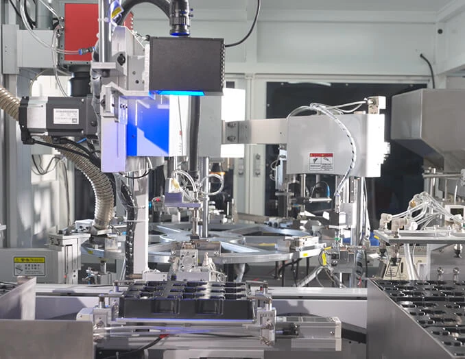
A cooling part is not successful merely because it fits the drawing. It must remove the required heat at the available coolant temperature and flow while staying within the server manufacturer’s limits. The evaluation should cover five linked outcomes:
The right supplier may be a specialist in copper cold plates, aluminum heat exchangers, brazed assemblies, CNC-machined manifolds, vacuum-brazed components, or liquid-to-liquid cooling distribution units. A company that is excellent at one process is not automatically qualified for every cooling architecture.
A useful public reference is the Frontier supercomputer at Oak Ridge National Laboratory. ORNL identifies Frontier as an HPE Cray EX system using AMD Instinct MI250X accelerators, and the TOP500 project records its leadership position when it entered the list in 2022. The system uses direct liquid cooling as part of its high-density architecture. This is a documented deployment, not a private customer testimonial.
The lesson for a data center procurement team is straightforward: high-performance computing cooling is a system-level engineering problem. The cold plate, manifold, quick disconnect, hose, coolant distribution unit, monitoring system, and facility water loop must work together. A manufacturer that supplies only a metal component should not be evaluated as if it owns the complete cooling risk.
Before using this case as a design benchmark, verify the current technical information through the and publications. Do not copy Frontier’s design without checking your own server thermal limits, coolant chemistry, facility water conditions, and service requirements.
Prepare a technical requirement package before contacting suppliers. Without a common data sheet, each manufacturer will interpret the project differently, making price and performance comparisons unreliable.
Use a spreadsheet or procurement database to compare suppliers using the same fields. Prepare a thermal test plan, hydraulic test plan, drawing revision, approved-material list, inspection checklist, and supplier scorecard. If available, use computational fluid dynamics for early flow-distribution review, finite-element analysis for mechanical stress, and a thermal resistance model for component-level comparison.
A practical calculation is:
Thermal resistance, Rth = (Tsurface − Tcoolant) / Q
where temperature is in degrees Celsius and heat load is in watts, producing a result in K/W. Keep the measurement locations consistent. A thermal resistance value is not comparable if one supplier measures at the component surface and another measures at the semiconductor case.
Tools: thermal spreadsheet, server heat map, pump curve, coolant technical data sheet, and preliminary CAD model.
Action: Convert the project requirements into testable limits. Specify heat load, inlet temperature, flow rate, maximum outlet temperature, allowable pressure drop, and maximum surface temperature. Separate normal, minimum, and worst-case conditions.
Parameters: State the target heat load in watts, flow in L/min, pressure drop in kPa, and temperature in °C. Include tolerances rather than a single nominal value.
Check: Confirm that the design window is compatible with the facility pump, coolant distribution unit, server fittings, and maintenance procedure.
Failure fix: If the supplier cannot meet thermal performance without exceeding pressure-drop limits, ask for channel redesign, increased wetted area, parallel flow paths, improved interface flatness, or a different cooling architecture. Do not solve a hydraulic problem only by increasing pump speed.
Tools: supplier questionnaire, process-flow diagram, equipment list, quality manual, and audit checklist.
Action: Ask the Custom Thermal Cooling Parts Manufacturer to identify its actual production processes: CNC machining, vacuum brazing, friction-stir welding, diffusion bonding, extrusion, skiving, additive manufacturing, or another method.
Parameters: Request information about machine envelope, dimensional capability, joining method, inspection equipment, production capacity, and minimum order quantities. Ask which dimensions are measured on every part and which are sampled.
Check: Confirm that the proposed process can produce the required channel width, wall thickness, base thickness, flatness, port geometry, and surface finish. Review whether the same process has been used for comparable coolant pressure and heat-load conditions.
Failure fix: If capability is described only with broad claims such as “high precision,” request actual drawing tolerances, sample inspection reports, and capability data. If no evidence is available, classify the supplier as unqualified until a controlled sample is tested.
Tools: material certificates, coolant safety data sheet, compatibility charts, corrosion test plan, and seal-material specifications.
Action: Build a complete wetted-material list. Include copper or aluminum alloys, nickel plating, brazing filler, solder, stainless steel, elastomers, adhesives, coatings, and hose materials.
Parameters: Compare the material list with coolant pH, inhibitor package, temperature range, conductivity, dissolved oxygen, and expected service life. For single-phase water-glycol systems, confirm the required glycol concentration and inhibitor control from the coolant supplier rather than assuming a universal mixture.
Check: Require certificates of conformity and, where risk justifies it, static immersion or circulation testing. Examine corrosion products, discoloration, particle generation, seal swelling, and coolant property changes.
Failure fix: If compatibility is uncertain, do not approve production. Replace incompatible metals or elastomers, add a validated coating, change the coolant, or perform a longer circulation test with representative fittings and tubing.
Tools: 3D CAD viewer, 2D drawing, tolerance stack-up, design-for-manufacturing review, and finite-element or flow-analysis results.
Action: Review channel layout, inlet and outlet positions, mounting points, sealing surfaces, drainability, venting, service access, and adjacent-component clearance.
Parameters: Specify flatness at the thermal interface, surface roughness where relevant, port thread or fitting standard, O-ring groove dimensions, allowable mass, and maximum assembly torque.
Check: Confirm that the part can be installed without bending the board or applying side load to the server connector. Check that trapped air can be removed and that the lowest point can be drained during maintenance.
Failure fix: If the design traps air or creates uneven flow, revise the port orientation, add a vent or drain feature, change channel resistance, or use a manifold with measured balancing. If mounting distortion is observed, review the fastener pattern and torque sequence.
Tools: calibrated thermocouples or RTDs, flow meter, pressure transducers, power-controlled heater, coolant conditioning unit, data logger, and test fixture.
Action: Require the supplier to test a representative sample at defined heat loads and flow rates. The test fixture should reproduce the contact pressure, interface material, coolant direction, and boundary conditions expected in the product.
Parameters: Record inlet temperature, outlet temperature, surface temperature, heat input, flow rate, inlet pressure, outlet pressure, coolant chemistry, and ambient conditions. Calculate pressure drop as inlet pressure minus outlet pressure and thermal resistance using the same temperature definition for every sample.
Check: Review raw time-series data, calibration certificates, test uncertainty, sample identification, and test-article photographs. Confirm that steady-state criteria are stated rather than assumed.
Failure fix: If results cannot be reproduced, investigate sensor placement, heater contact, flow-meter accuracy, trapped air, coolant temperature stability, and fixture leakage. Repeat testing under a mutually approved protocol before comparing suppliers.
Tools: pressure-test bench, calibrated gauge, helium leak detector where required, dry-air or nitrogen source, hydrostatic equipment, and inspection microscope.
Action: Define separate proof, leak, and burst tests. Use the customer’s approved safety procedure and the component’s material limits. For production parts, establish whether every unit receives a pressure or leak test.
Parameters: State test medium, pressure, hold time, temperature, acceptance limit, and pass/fail method in the control plan. Never substitute a pressure value from another project without engineering approval.
Check: Verify that ports, welds, brazed joints, plugs, seals, and hidden channels are included. Inspect for permanent deformation after proof testing.
Failure fix: If leakage occurs, quarantine the part, identify the location, perform root-cause analysis, and verify the corrective action on new samples. Do not rework and ship a leaking part without documented requalification.
Tools: particle-counting method, filtered rinse equipment, microscope, cleanliness specification, and controlled packaging area.
Action: Define the required internal cleanliness level and cleaning sequence. The supplier should explain machining-fluid removal, deburring, rinsing, drying, capping, and packaging.
Parameters: Specify particle-size limits, residue limits, packaging condition, and storage period. Match the requirement to the pump, microchannels, filters, and server valves used in the system.
Check: Review rinse-water or extraction results, visual inspection records, and packaging photographs. Confirm that protective caps remain attached until installation.
Failure fix: If particles are found, isolate the batch and identify whether the source is machining chips, braze residue, plating debris, packaging fiber, or corrosion. Improve deburring and cleaning before repeating the acceptance inspection.
Tools: supplier audit form, nonconformance log, calibration list, control plan, and sample traceability records.
Action: Review incoming-material inspection, first-article inspection, in-process checks, final inspection, calibration management, employee training, and engineering-change control.
Parameters: Require lot or serial traceability linking the part to material certificates, machine or work center, operator or inspection record where appropriate, test result, and shipment date.
Check: Ask the supplier to demonstrate retrieval of records for one completed sample. Check whether nonconforming products are physically controlled and whether corrective actions include effectiveness verification.
Failure fix: If records are incomplete, use a conditional approval with a written corrective-action deadline, or select another supplier. A low unit price does not compensate for an untraceable coolant leak in a live data center.
Tools: production-capacity model, lead-time tracker, dual-source assessment, business-continuity questionnaire, and packaging validation plan.
Action: Run a pilot batch using production-intent equipment, materials, tooling, inspection, and packaging. Measure yield, rework, cycle time, and test failures.
Parameters: Agree on forecast horizon, minimum order quantity, safety stock, approved substitute materials, tooling ownership, change-notification period, and escalation contacts.
Check: Compare pilot results with prototype results. Confirm that performance does not decline when production volume increases.
Failure fix: If yield falls, identify the process step causing variation. Possible actions include fixture redesign, tighter cleaning controls, automated inspection, additional operator training, or a revised tolerance that preserves thermal performance.
When reviewing Onlink or another supplier, use evidence-based questions rather than brand recognition. Ask for the exact process, material, test method, and acceptance limit proposed for your part. Public product pages can help identify whether a company offers cold plates, heat exchangers, liquid cooling assemblies, or related components, but they do not replace project-specific qualification.
| Evaluation area | Evidence to request | Reason it matters |
|---|---|---|
| Thermal design | Thermal model, test report, heat-load map, measurement uncertainty | Shows whether the part removes heat under defined conditions |
| Hydraulics | Pressure-drop curve, flow-distribution data, test-fluid details | Prevents pump overload and under-cooled parallel branches |
| Leak control | Pressure-test method, leak limit, sample records, corrective actions | Reduces the risk of liquid release near electronics |
| Materials | Material certificates, coolant compatibility assessment, seal data | Controls corrosion, swelling, particles, and long-term degradation |
| Production quality | Control plan, capability data, calibration records, traceability sample | Shows whether prototype results can be repeated in volume |
| Commercial continuity | Capacity plan, lead time, change-control procedure, contingency plan | Protects deployment schedules and spare-part availability |
Problem: A low quotation may exclude testing, tooling, cleaning, packaging, documentation, or engineering changes.
Solution: Request a total-cost quotation that separates prototype tooling, production tooling, testing, inspection, packaging, logistics, and recurring unit price.
Problem: Thermal resistance changes with sensor location, interface material, mounting force, heat source, and coolant condition.
Solution: Issue one customer-controlled test method and require the same boundary conditions for every supplier.
Problem: A narrow-channel cold plate may produce a low component temperature but require excessive pump power.
Solution: Set a maximum pressure-drop limit and review the complete pump-system curve, not only the component result.
Problem: A hand-finished prototype may not represent brazing voids, machining variation, cleaning quality, or inspection speed during mass production.
Solution: Require production-intent samples before final approval and compare first-article results with pilot-batch results.
Problem: “Water cooling” does not identify pH, inhibitor package, glycol concentration, conductivity, or filtration.
Solution: Name the coolant formulation or define its measurable chemical limits, then validate every wetted material and seal.
Problem: A part can pass a laboratory test yet create long maintenance times because it traps air or cannot be drained.
Solution: Review installation, venting, draining, quick-disconnect access, replacement procedure, and spill-control requirements with the operations team.
Use a staged approval process: specification review, supplier capability audit, design review, prototype testing, production-intent pilot, reliability validation, and commercial release. Score each Custom Thermal Cooling Parts Manufacturer against documented data rather than adjectives. The strongest supplier is the one that can connect custom liquid cooling parts for data centers to measurable thermal resistance, pressure drop, leak rate, cleanliness, material compatibility, and traceability—and can repeat those results at production volume. Whether the candidate is Onlink or another data center cooling component supplier, require evidence for cold plates, heat exchangers, and thermal interface materials under the same boundary conditions before approval.


