Sep.17,2026
For a Precision Metal Stamping Manufacturer, tooling design determines much more than the shape of a stamped part. It affects dimensional accuracy, production speed, material utilization, die life, maintenance frequency, defect rates, and the total cost per part. Buyers searching this topic usually want practical guidance for selecting a die structure, estimating tooling investment, preventing production problems, and comparing suppliers.
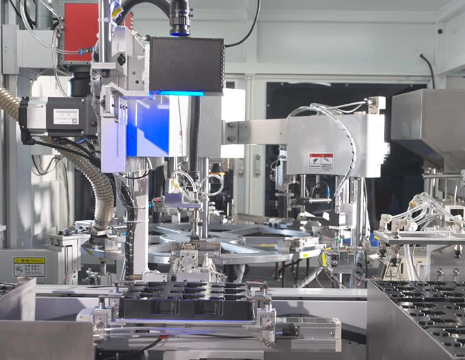
This guide explains how to evaluate tooling design step by step, what purchasing teams should request from suppliers, which tools are required for validation, and which common mistakes increase cost in high-volume production. Onlink uses engineering review, tooling analysis, and production control to help customers balance precision and cost. For reference, include the following product and tooling image when publishing the article:
A stamping die is a production system, not simply a cutting or forming block. Its layout determines how the material moves through the process, how accurately each feature is positioned, and how quickly the press can operate.
A low initial tooling price may create a higher total cost if the die requires frequent repairs, produces excessive scrap, or cannot maintain tolerance at production speed.
Purchasing teams normally evaluate the complete cost of ownership. Their main concerns include the initial die price, piece price, production capacity, delivery risk, maintenance cost, and the supplier's ability to support engineering changes.
Before comparing quotations, request the following information:
High-volume buyers may accept a higher initial die investment if it lowers the unit cost over the expected production quantity. A simple break-even calculation can show when a more advanced tool becomes economical.
Use this calculation:
Break-even quantity = Additional tooling investment / Unit cost reduction
For example, if a progressive die costs 20,000 dollars more than a simpler transfer tool but reduces the unit cost by 0.04 dollars, the break-even quantity is 500,000 parts. If the program will produce several million parts, the higher initial investment may be financially justified.
Buyers are concerned when parts pass inspection during initial samples but drift out of tolerance after extended production. Common causes include heat buildup, material variation, punch wear, guide wear, incorrect clearances, and unstable coil feeding.
A supplier should explain how the die will control variation through:
High-volume production magnifies every maintenance problem. A small component that takes two hours to replace can cause significant lost output when the press runs continuously.
Ask the tooling designer to identify:
Material cost is often one of the largest expenses in stamping. A poorly arranged strip can create excessive carrier width, unusable skeleton material, unnecessary pilot holes, or a high number of rejected parts.
Before approving the tool, request a strip layout showing:
A tolerance printed on a drawing is not enough to guarantee production capability. The supplier must connect the tolerance to the die design, measurement method, material condition, and process controls.
For critical features, ask for:
Die clearance is the space between the punch and die cutting edges. It must match the material type, thickness, tensile strength, and required edge condition.
Insufficient clearance can cause:
Excessive clearance can cause:
The correct clearance should be calculated during tool design and confirmed through tryout samples. It should not be selected only from a general rule of thumb.
Guide posts, guide bushings, pilots, and precision plates keep the die sections aligned as the press cycles. A stable guiding system is especially important when the tool contains multiple forming and piercing stations.
When reviewing the design, confirm:
In progressive stamping, the order of operations controls how the strip is supported and how forces are distributed. A good station sequence may separate heavy forming operations, use pilots before critical cuts, and avoid removing support before the part is stable.
A typical sequence may include:
The exact sequence depends on the material, geometry, tolerance, and press capacity. Moving a forming operation to a different station can improve accuracy without changing the finished part design.
Forming operations require controlled material flow. If the material cannot move as planned, the part may crack, wrinkle, twist, or spring back beyond the allowed tolerance.
Tooling engineers should evaluate:
Tool material should be selected according to production volume, material abrasiveness, required edge life, and forming load. High-volume tools often use hardened tool steels or carbide inserts in high-wear areas.
Possible design choices include:
The most expensive material is not always the best choice. The correct solution combines tool material, geometry, lubrication, maintenance access, and expected production volume.
A progressive die performs several operations as the strip advances through the press. It can produce large quantities with limited manual handling and consistent cycle timing.
Advantages include:
Progressive dies may require higher initial engineering cost and more complex maintenance. They are usually most suitable when the design is stable and annual volume is high enough to justify the investment.
Transfer dies move individual blanks or partially formed parts between stations. They are useful when the part cannot remain connected in a coil strip or when the geometry requires substantial forming space.
Transfer tooling may be preferred when:
The buyer should compare transfer tooling with progressive tooling based on total cost, not only the die quotation. Include automation, press requirements, labor, cycle time, material utilization, and maintenance.
A compound die performs more than one cutting operation at the same station. It can provide accurate relationships between features when the part is relatively flat and the process is not highly complex.
Compound dies may reduce:
They may be less suitable for parts requiring multiple forming directions or complex three-dimensional shapes.
Small changes to the part design can greatly simplify the die. Before cutting steel, review whether the design includes practical radii, accessible features, realistic tolerances, and suitable datum references.
Potential cost reductions include:
Start with complete technical information. A supplier cannot select the correct die structure from a two-dimensional outline alone.
Prepare the following data:
Separate the part features into cutting, bending, forming, drawing, coining, and tapping operations. This classification helps determine whether the part is suitable for progressive, transfer, compound, or multi-operation tooling.
Mark each feature as one of the following:
This prevents the tooling team from spending money to control dimensions that do not affect the product.
Create a preliminary strip layout before finalizing the tool architecture. Check the number of parts per pitch, carrier stability, scrap bridges, grain direction, and station spacing.
Compare possible tooling solutions against volume, geometry, tolerance, press availability, and maintenance requirements.
| Tooling type | Best application | Main advantage | Main consideration |
|---|---|---|---|
| Progressive die | Small to medium parts with high volume | High output and low handling cost | Higher design complexity and initial investment |
| Transfer die | Large, deep, or three-dimensional parts | Flexible forming capability | Requires transfer automation and accurate timing |
| Compound die | Flat parts with multiple cutting features | Good feature-to-feature accuracy | Limited flexibility for complex forming |
| Simple die set | Low-volume or repeated single operations | Lower initial tooling cost | Higher handling and labor cost |
Estimate the force required for piercing, blanking, bending, forming, and stripping. Add a safety margin so the press is not operated continuously at its maximum capacity.
Review these conditions:
Operating a tool on an unsuitable press can create deflection, poor alignment, inconsistent forming, and premature component failure.
Maintenance planning should be completed before tool fabrication. Every expected wear area should have a replacement strategy.
Use three-dimensional design review and forming analysis where the geometry or material presents a high risk of cracking, wrinkling, springback, or interference.
The review should confirm:
Resolve design questions before machining. Engineering changes after steel cutting are more expensive and can delay the production launch.
After design approval, the supplier should control material certification, machining, heat treatment, surface treatment, and assembly.
Request documentation for:
Tool tryout should use the actual production material whenever possible. Test the die at increasing speeds instead of immediately running at full speed.
Do not approve the tool based only on a few visually acceptable samples. Validate the process at a production-representative quantity.
The approval package should include:
Annual quantity is important, but it is not the only decision factor. Part geometry, tolerance, material, press availability, automation, and product life also affect the correct tool choice.
To avoid this mistake, compare at least two tooling concepts using total cost per part, expected maintenance, output rate, material utilization, and launch risk.
Overly tight tolerances increase machining, inspection, adjustment, and maintenance costs. They may also reduce tool life if the process must be continuously corrected.
Classify tolerances according to function and maintain tight control only where it is technically necessary.
Material thickness, hardness, tensile strength, coating, and grain direction can vary between lots. A die designed around ideal material may fail when the actual coil condition changes.
Specify acceptable material ranges and validate the tool using production-grade material from an approved source.
A narrow or weak carrier can twist, buckle, or shift during feeding. This affects every station and may cause progressive dimensional errors.
Improve carrier stability through better strip layout, stronger bridges, suitable pilot locations, and controlled feed settings.
If the strip is not accurately located before a critical operation, the resulting feature may shift even when the press and die are correctly aligned.
Use pilots and reliable reference features before operations that determine final part accuracy.
A die with inaccessible wear components may appear economical during quotation but become expensive during production. Maintenance time, lost output, and emergency machining can exceed the original savings.
Include maintenance access, standard components, spare parts, and replacement procedures in the design review.
A short trial may not reveal heat buildup, progressive wear, sensor faults, coil variation, or scrap accumulation. Run a longer trial that reflects the expected production condition.
Tool ownership, repair responsibility, storage, modification approval, and spare part costs should be clearly defined in the purchase agreement.
Include the following contractual items:
Different suppliers may quote different processes, making direct price comparison unreliable. Give each supplier the same drawings, material data, forecast volume, tolerance requirements, press information, and quality standards.
Ask each supplier to provide:
Visit the supplier or request evidence of similar work. Review the supplier's experience with comparable materials, tolerances, part sizes, volumes, and press speeds.
Useful evidence includes:
A scorecard helps purchasing teams avoid choosing a supplier based only on the lowest quotation.
The weighting should be adjusted according to the product risk and customer requirements.
The best tooling decision balances initial investment, production speed, material efficiency, quality performance, maintenance, and future support. A die that is inexpensive to build but unreliable in production is not a low-cost solution.
Use the following sequence when making the final decision:
High-volume metal stamping achieves the best results when tooling design, part design, material selection, press capability, inspection, and maintenance are evaluated together. Working with an experienced Precision Metal Stamping Manufacturer such as Onlink can help purchasing teams reduce avoidable tooling risk while maintaining stable precision and competitive production cost.


