Oct.30,2026
For OEM engineers developing sealed connectors, sensor housings, threaded bosses, or structural assemblies, a metal insert overmolding design guide turns a difficult assembly decision into a controlled manufacturing plan. The goal is to apply practical DFM rules for OEM engineers before tooling begins, select qualified custom metal insert molding services, and verify insert molding, thermoplastic injection molding, and mold flow analysis together. The critical controls include overmold geometry, draft angle, and measured pull-out force rather than visual judgment alone.
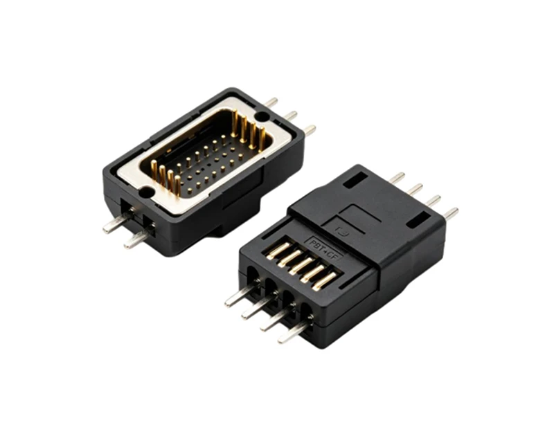
Metal insert overmolding is used when a product needs the conductivity, stiffness, wear resistance, or dimensional stability of metal together with the insulation, sealing, and impact resistance of a polymer. Typical applications include copper terminals in automotive connectors, stainless-steel threaded inserts in appliance housings, aluminum reinforcement plates in handheld equipment, and brass bushings in precision mechanisms.
The process can replace several secondary operations. A conventional assembly may require a molded housing, a press-fit insert, adhesive, manual alignment, and post-assembly inspection. Overmolding integrates these functions during injection. That can reduce part count and handling, but it also moves risk into the mold design and material-selection stages. A misplaced insert, insufficient polymer coverage, or excessive injection pressure can produce short shots, flash, distortion, cracking, or a weak metal-to-plastic interface.
For this reason, the best metal insert overmolding design guide is not limited to choosing a resin. It addresses the complete chain: functional requirements, insert geometry, tolerances, fixture design, polymer behavior, mold filling, cooling, ejection, inspection, and validation. Onlink can support this process by reviewing the product concept before the tooling configuration is frozen.
In standard injection molding, the cavity is empty when molten polymer enters. In insert molding, a metal component is positioned in the cavity first. The mold then closes, polymer flows around the insert, and the finished component is ejected after cooling. The insert may be loaded manually, placed by a robot, or fed through an automated mechanism.
“Overmolding” describes the polymer layer formed around or over a pre-existing component. “Insert molding” is the broader process category. The insert can be metal, fabric, wire, ceramic, or another molded part, although metal inserts are especially common where electrical or mechanical performance is required.
Most metal-to-polymer retention comes from mechanical interlock rather than chemical bonding. Polymer flows around holes, grooves, undercuts, knurls, or flanges and forms a physical lock after solidification. Adhesion may contribute when the metal surface and polymer chemistry are compatible, but it should not be treated as the only retention mechanism unless laboratory testing supports that assumption.
Three forces must be considered separately:
A simplified estimate for a straight cylindrical interface is:
Fpull-out ≈ πDLτinterface
where D is the effective insert diameter, L is the embedded length, and τinterface is the effective shear strength of the polymer-interface system. This equation is only a preliminary estimate. Knurls, ribs, holes, weld lines, polymer shrinkage, temperature, and loading rate can change the measured result substantially.
Begin with the load case, not the insert shape. Record tensile force, torsional torque, bending moment, vibration profile, operating temperature, humidity, chemical exposure, and expected service life. A threaded brass insert used for a 2 N·m screw-tightening torque needs a different retention design from a terminal carrying a 30 A current.
Convert the requirement into measurable acceptance criteria. For example, specify a minimum axial pull-out force of 450 N at 23°C, a minimum torque resistance of 1.8 N·m, and no cracking after 500 thermal cycles from −40°C to 125°C. These values are examples of a validation format; the actual limits must come from the product risk analysis and applicable industry requirements.
For electrical parts, add contact resistance, dielectric withstand voltage, creepage distance, and insulation resistance. For sealing parts, define leakage pressure, compression set, and ingress-protection requirements. Without these values, an insert can appear secure while failing its real function.
Material selection should consider temperature, chemical resistance, moisture absorption, shrinkage, and coefficient of thermal expansion. Common combinations include:
| Metal insert | Typical polymer choices | Important considerations |
|---|---|---|
| Brass or copper | PA, PBT, PPS, LCP | Electrical conductivity, oxidation, soldering temperature, moisture sensitivity |
| Stainless steel | PA, POM, PC, PEEK | Surface adhesion, high stiffness, corrosion resistance, thermal cycling |
| Aluminum | PC/ABS, PA, PBT | Surface treatment, differential shrinkage, galvanic corrosion risk |
| Carbon steel | PP, PA, ABS, TPE | Plating, rust prevention, insert preheating, interface durability |
Polyamide can absorb several percent moisture by weight depending on grade and conditioning history, which changes dimensions and mechanical performance. PBT generally offers better dimensional stability in humid environments, while PPS and LCP are often selected for elevated temperatures and electrical applications. The resin supplier’s grade-specific data sheet should control the final decision.
When the metal and polymer have significantly different thermal expansion coefficients, residual stress may concentrate at sharp transitions. A compliant TPE layer, a longer flow path, rounded geometry, or mechanical locking features may be required to prevent interface separation.
A smooth cylindrical insert is easy to manufacture but may depend heavily on polymer shrinkage and surface friction. More reliable designs use controlled mechanical features:
Avoid abrupt, thin-edged undercuts that create high stress in the polymer or prevent clean ejection. A groove that is too deep can produce a thin polymer section prone to cracking. A feature that is too shallow may not provide sufficient resistance after molding. The correct depth depends on resin shrinkage, wall thickness, insert diameter, and the required mechanical load, so prototype testing is essential.
Use radii at transitions wherever the application permits. A radius of 0.5 mm instead of a sharp internal corner can significantly reduce local stress concentration, although the final value must fit the insert manufacturing process and available cavity steel.
Uniform polymer thickness improves filling and cooling. For many engineering thermoplastics, a nominal wall between 1.5 and 3.0 mm is a practical starting range, but the allowable range depends on resin grade, flow length, glass-fiber content, and cosmetic requirements. Thick sections can create sink marks and voids; thin sections can freeze before the cavity is filled.
When the insert is surrounded by polymer, maintain enough cover to prevent exposure after shrinkage, machining variation, and handling. A preliminary cover thickness of approximately 1.0 to 1.5 mm may be suitable for some non-structural features, while high-load or high-voltage designs may require more. Electrical clearances must be calculated separately from mechanical cover thickness.
Use draft on all surfaces parallel to the mold opening direction. A common starting point is 0.5° to 1° per side for polished surfaces and 1° to 3° per side for textured surfaces. Glass-filled polymers, deep cavities, and strong mold textures may require additional draft. If the design uses a straight-sided insert that must remain precisely located, place the draft in the surrounding polymer geometry rather than compromising the functional metal interface.
The insert should never rely only on operator hand placement or friction against the cavity. Design a locating fixture with positive stops, anti-rotation features, and sufficient clearance for polymer flow. The fixture must support the insert against injection pressure without creating an unwanted witness mark on a sealing or cosmetic surface.
Calculate the projected area exposed to injection pressure:
Clamp force requirement ≈ projected area × cavity pressure × safety factor
If the projected area is 1,200 mm², estimated cavity pressure is 60 MPa, and the selected safety factor is 1.2, the theoretical separating force is approximately 72 kN. The mold and machine must provide additional margin for pressure variation, wear, and process instability.
Use poka-yoke features so the insert cannot be loaded upside down or in the wrong orientation. For high-volume production, sensors can verify insert presence and position before mold closing. A missing insert should trigger a machine stop or automatic reject rather than produce a visually acceptable but functionally defective part.
Gate location determines how polymer reaches the insert. The flow should not strike a thin metal edge at high velocity if that could displace the insert or create jetting. A balanced flow front reduces differential pressure and helps prevent insert movement.
Vents should be located near the final fill areas, especially around closed pockets and insert shoulders. Typical vent depths depend on the resin, mold steel, and supplier recommendations; many thermoplastic molds use vent depths in the approximate range of 0.02 to 0.05 mm. Excessive vent depth can cause flash, while insufficient venting can cause burn marks, short shots, and trapped gas.
Weld lines near a highly loaded insert deserve special attention. A weld line may have lower strength than the bulk polymer because the flow fronts meet after partial cooling and may not fully knit. Mold flow analysis can predict weld-line position, air traps, pressure, and filling time before cutting steel.
A useful simulation should evaluate fill time, pressure at the end of fill, clamp tonnage, cooling time, warpage, weld lines, air traps, and insert displacement risk. The analysis becomes more reliable when it includes the actual resin grade, fiber orientation model, insert geometry, gate design, and mold temperature.
Do not treat simulation as a replacement for testing. It is a design-screening tool that helps compare alternatives. A 0.8-second fill time may reduce freezing in a thin wall, but it could also increase shear heating or insert movement. The final process window must be proven with molded parts.
For a connector, the terminal location may need a position tolerance of ±0.10 mm, while a cosmetic polymer edge may accept ±0.30 mm. The tolerance must reflect function and process capability rather than drawing convenience.
Stamped inserts may require burr orientation control because a burr on the cavity-contacting side can create flash or prevent seating. Machined inserts may provide tighter geometry but can increase piece cost. The correct choice depends on annual volume, dimensional requirements, and the number of overmolding operations.
Core pins that support a metal insert can improve dimensional control, but they may also create flow shadows or knit lines. A mold review should examine both the nominal geometry and the worn condition after production hours have accumulated.
For engineering materials, mold temperature can influence weld-line strength, surface finish, crystallinity, and shrinkage. Cooling time should be long enough to prevent deformation during ejection, but excessive cooling reduces productivity without necessarily improving quality. A documented process window is more valuable than a single “approved” machine setting.
If a critical dimension has a total tolerance of 0.20 mm, a process standard deviation of 0.025 mm gives a potential six-sigma spread of 0.15 mm before considering centering. That may be acceptable or inadequate depending on the specification and capability target. Capability should be calculated from actual production data, not from a small set of hand-selected samples.
Insert movement is usually linked to unbalanced flow, inadequate fixture support, excessive injection speed, or insufficient clamping around the insert. Review the projected pressure area, add a positive stop, change the gate direction, or use staged filling. Do not simply increase holding pressure; that may intensify flash and residual stress.
Flash can result from parting-line mismatch, worn shutoff surfaces, insert dimensional variation, excessive cavity pressure, or debris on the locating face. Measure the insert and mold shutoff separately. If flash appears only on one cavity, compare cavity alignment and wear rather than changing the entire process.
Cracking often develops where a rigid insert blocks polymer shrinkage. Sharp metal corners, thin polymer cover, high glass-fiber orientation, and a large thermal-expansion mismatch increase the risk. Add radii, increase local polymer thickness, redesign the retention feature, select a tougher resin, or introduce a compliant transition.
Voids are commonly associated with thick sections and insufficient packing, while sink marks occur when the outer skin cools before the internal material. Short shots may be caused by low melt temperature, premature gate freeze, inadequate venting, or excessive flow length. Use a balanced wall design, improve venting, adjust gate size, and verify resin drying.
Low retention may come from a smooth insert, insufficient embedded length, poor surface cleanliness, incorrect polymer grade, or a weld line at the load path. Compare a smooth insert with a knurled or grooved sample, then test the change under the actual temperature and loading conditions. A room-temperature result alone cannot represent performance in a hot engine compartment or outdoor enclosure.
A designed experiment can reveal interactions that single-variable trials miss. Useful factors include melt temperature, mold temperature, injection speed, holding pressure, cooling time, insert preheat temperature, and fixture design. Responses may include insert position, pull-out force, warpage, flash height, and cycle time.
For example, a two-level screening study can identify whether insert preheating improves pull-out force but increases cycle time. A response-surface design can then optimize the temperature and holding-pressure combination. Record both average performance and variation; a setting that produces a high mean pull-out force with a wide distribution may be less suitable than a slightly lower but stable result.
Preheating can reduce the temperature difference between the insert and molten polymer, improve wetting, and lower local freeze-off. However, it adds equipment, handling time, oxidation risk, and operator-safety requirements. The insert temperature should be measured and controlled rather than estimated from heater settings.
Preheating is especially relevant for large metal inserts, high-temperature polymers, and designs where premature polymer freezing prevents complete encapsulation. It should be validated against insert displacement, cycle time, surface condition, and final mechanical performance.
Automation requires repeatable insert presentation. Add lead-in chamfers, consistent reference datums, part-detection targets, and sufficient gripper clearance. Avoid geometries that can nest, overlap, or rotate unpredictably in a feeder bowl.
For high-volume production, monitor insert presence, mold position, cavity pressure, injection stroke, and ejection confirmation. Statistical process control can then distinguish a random loading error from gradual fixture wear or a drifting injection condition.
A witness mark from an insert fixture may be acceptable on an internal surface but unacceptable on a customer-facing panel. Mark these zones clearly in the drawing and inspection plan. Cosmetic standards should define allowable flash height, gate vestige, discoloration, sink depth, and surface-flow marks with reference samples or measurable limits.
When comparing suppliers, ask for evidence rather than general claims. A capable supplier should be able to explain:
Onlink can be considered when the project needs design-for-manufacturing review, mold development, metal insert preparation, injection molding, assembly integration, and inspection planning in one coordinated workflow. Provide a 3D model, 2D drawing, annual volume, material requirements, load conditions, and target validation tests so the quotation reflects the actual technical scope.
A reliable metal insert overmold is created before the first production shot. Define the loads, select compatible materials, add mechanical retention, maintain suitable wall thickness and draft, locate gates and vents intelligently, secure the insert with a positive fixture, and validate the finished assembly under real temperature and loading conditions. The most effective metal insert overmolding design guide combines DFM rules for OEM engineers with qualified custom metal insert molding services, while controlling insert molding, thermoplastic injection molding, and mold flow analysis. Confirm the overmold geometry, draft angle, and measured pull-out force with production-representative data, then contact Onlink to review your next insert overmolding project.


