
When an EV program moves from 5,000 to 200,000 packs per year, the choice between stamped battery busbars for high-volume EV production and CNC-machined battery busbars for EV packs affects more than piece price. It influences current capacity, thermal behavior, dimensional repeatability, and launch risk. An experienced EV Battery Pack Components Manufacturer evaluates the copper busbar, cell interconnect, and battery management system interface together, using progressive-die stamping, CNC milling, and electrical resistance measurements rather than appearance alone. This comparison addresses the practical questions engineers and purchasing teams ask: Which process scales better? When is CNC worth the premium? Can stamped parts meet tight battery-pack tolerances? And which option gives a safer production path?
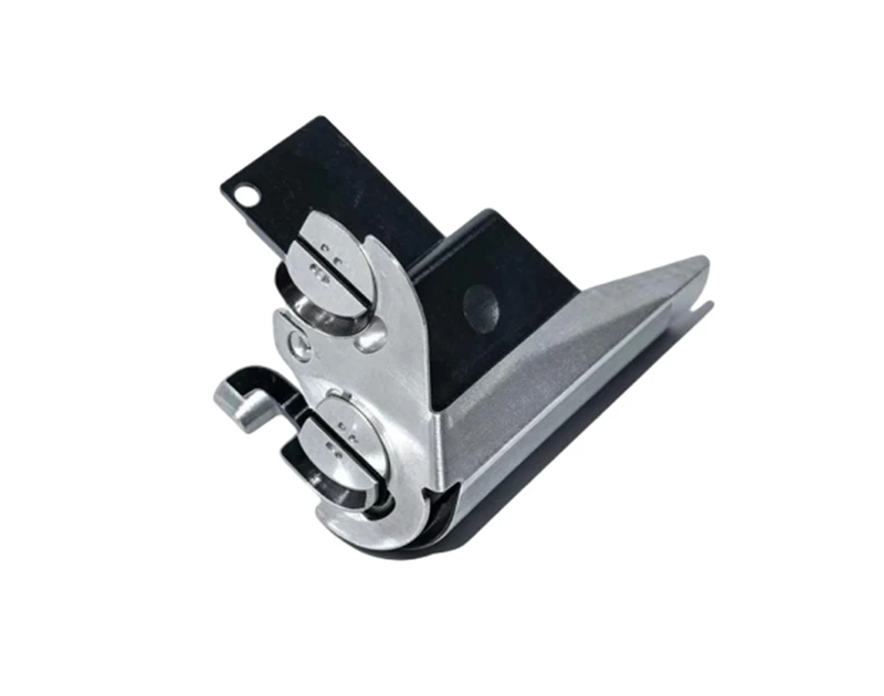
Why EV Battery Pack Components Manufacturers Compare Stamping and CNC Processing
The decision usually begins with a production problem rather than a machining preference. A battery developer may have a reliable prototype made from CNC-cut copper, yet discover that a 16-minute machining cycle is incompatible with a line producing several hundred packs per shift. Another team may select stamping too early, only to face tooling changes when cell spacing, fuse geometry, or service disconnect requirements are revised.
Both processes can produce conductive interconnects, but they are optimized for different stages of an EV program:
- Progressive-die stamping forms high quantities of flat or moderately three-dimensional busbars through a sequence of punching, bending, coining, and forming operations.
- CNC milling or routing removes material from copper, aluminum, or laminated stock and is suited to prototypes, low-volume production, and complex geometries.
- Laser cutting, although not the focus of this comparison, is often used between prototype and mass-production stages when a customer needs lower tooling commitment.
For a high-voltage pack, busbar design must also account for creepage distance, clearance, dielectric insulation, weldability, short-circuit behavior, and the measurement leads used by the battery management system. A lower component price is not a saving if it increases assembly rework or creates resistance variation at a welded joint.
Stamped Battery Busbars Versus CNC Battery Busbars: Parameter Comparison
The following values are engineering ranges commonly used for initial feasibility studies. Actual performance depends on conductor alloy, thickness, geometry, tooling condition, surface treatment, and the customer’s inspection standard. They should be confirmed by drawing review and sample validation.
| Parameter | Progressive-die stamped busbar | CNC-processed busbar | Production implication |
|---|---|---|---|
| Typical application volume | 50,000 to more than 1,000,000 parts per year | 1 to approximately 50,000 parts per year | Stamping becomes more economical as annual volume increases. |
| Typical piece-part cycle | About 0.2 to 3 seconds per part after setup, depending on press speed and operations | About 2 to 20 minutes per part, depending on material removal and fixturing | Stamping supports automated pack assembly; CNC may require more parallel equipment. |
| Initial tooling investment | Approximately US$20,000 to US$200,000 for a dedicated progressive die, depending on complexity | Usually low dedicated-tooling cost; fixtures and programming may range from US$500 to US$10,000 | CNC reduces initial commitment, while stamping spreads tooling cost across a large quantity. |
| Dimensional repeatability | Commonly ±0.05 to ±0.15 mm for controlled features | Commonly ±0.02 to ±0.10 mm for accessible milled features | CNC may offer tighter local tolerances; stamping can provide adequate repeatability at higher speed. |
| Material utilization | Often 60% to 90%, depending on nesting and carrier design | Often 30% to 80%; deep pockets can generate substantial chip waste | Copper and aluminum scrap value should be included in the cost model. |
| Edge condition | May include a 5% to 15% burr ratio of material thickness if not deburred or controlled | Usually lower burr height after optimized cutting, but tool wear can change the result | Insulation and high-voltage clearance require documented burr limits. |
| Design change flexibility | Low to moderate after die release; engineering changes may require die inserts or rework | High; geometry can often be changed through CAD and CAM updates | CNC is safer during an unstable design phase. |
| Surface treatment compatibility | Nickel, tin, silver, or selective plating can be integrated after forming | Supports the same finishes, although machining marks may require additional preparation | Contact resistance and corrosion protection must be tested after plating. |
| Best cost position | Usually after tooling amortization and stable demand | Usually for prototypes, spare parts, engineering builds, and short runs | Break-even depends on tooling cost, piece price, scrap, and forecast accuracy. |
Electrical and Thermal Performance for EV Battery Pack Components
Process selection does not determine conductivity by itself. Alloy, cross-sectional area, joint quality, and temperature determine the electrical result. For a straight conductor, resistance can be estimated using R = ρL/A, where ρ is material resistivity, L is conductor length, and A is cross-sectional area.
For example, a copper busbar measuring 300 mm long with a 20 mm² cross-section has an approximate room-temperature resistance of 0.25 mΩ when copper resistivity is taken as 1.68 × 10⁻⁸ Ω·m. At 300 A, the idealized I2R loss is about 22.5 W before contact resistance, temperature rise, and current distribution are included. A small reduction in cross-section caused by a slot, bend radius, or punched feature can therefore create a measurable hot spot.
In practice, the manufacturer should report:
- Four-wire milliohm resistance at a defined temperature;
- Temperature rise at the customer’s continuous and peak current;
- Weld pull strength or joint shear strength;
- Plating thickness and surface roughness where electrical contact is required;
- Insulation withstand voltage and insulation resistance after forming;
- Burr height, flatness, hole position, and bend angle.
A stamped busbar can match a CNC busbar electrically when the same alloy, cross-section, surface finish, and joining process are used. CNC does not automatically produce a lower-resistance part, and stamping does not automatically produce a less reliable part. The controlling factor is process capability demonstrated by inspection data.
Scenario Fit: Which EV Battery Pack Busbar Process Works Better?
Prototype and Pilot Packs: CNC Processing Has the Lower Design Risk
During a prototype build, cell spacing and module architecture may change every few weeks. CNC processing allows a designer to alter hole locations, slots, tabs, and sensor branches without rebuilding a progressive die. For a pack using 20 to 100 busbars per vehicle, the higher piece price may be acceptable because avoiding a premature tooling commitment protects the engineering budget.
A practical workflow is to machine the first articles, inspect them with a coordinate-measuring machine, validate resistance and insulation, and then freeze the geometry. Once the design has passed vibration, thermal cycling, and high-voltage isolation tests, the program can move to stamped production.
Stable High-Volume EV Production: Stamping Usually Wins on Throughput
Consider a pack containing 48 copper interconnects and an annual requirement of 100,000 packs. That equals 4.8 million busbars before service parts and scrap are considered. If CNC processing requires an average of six minutes per part, the theoretical machining requirement exceeds 480,000 equipment hours. Even with multiple machines and operators, the labor, fixturing, chip handling, and inspection burden becomes substantial.
A progressive stamping line operating at 60 strokes per minute may produce one or several parts per stroke, depending on the die layout. After accounting for coil loading, quality checks, and downtime, a single line can support a significantly higher annual quantity than a standalone CNC cell. The exact output must be calculated from strokes per minute, cavities, uptime, and first-pass yield rather than from press speed alone.
Complex Laminated and Three-Dimensional Busbars
CNC is often the better starting point for thick copper, laminated conductors, complex pockets, and parts with several non-planar levels. It can remove material around sensor channels or create features that are difficult to form without cracking. However, machining may expose more cut surfaces, create directional tool marks, and increase the need for deburring and cleaning.
Stamping is more attractive when the busbar is made from strip stock and its bends can be distributed across controlled forming stations. A design review should check minimum bend radius, grain direction, springback compensation, pilot-hole accuracy, and the distance between punched features and the strip edge.
Price Analysis for Stamped and CNC-Processed EV Busbars
Comparing quoted piece prices alone can lead to the wrong decision. A useful total-cost model is:
Total cost = material + processing + labor + tooling amortization + plating + inspection + packaging + scrap + changeover and logistics costs.
Suppose a stamped busbar costs US$0.42 per piece after plating, while a CNC version costs US$2.80. A progressive die costs US$75,000, and the customer expects 500,000 parts. Tooling adds US$0.15 per part when fully amortized, producing an indicative stamped cost of US$0.57 per part before other program-specific costs. At 10,000 parts, tooling alone contributes US$7.50 per piece, making CNC potentially more economical.
These figures are examples for understanding the break-even principle, not a universal quotation. The true break-even quantity can be estimated as:
Break-even volume = (stamping tooling cost + validation cost) ÷ (CNC unit cost − stamped unit cost).
Purchasing teams should also ask whether the quotation includes copper weight, plating, deburring, vision inspection, packaging separators, engineering-change support, and replacement tooling. A low quote that excludes final inspection may become expensive after a field-return problem.
Customer Experience: What Production Teams Commonly Report
The following anonymized cases represent typical project experiences discussed during supplier evaluations. They are presented as engineering case summaries rather than independently audited public testimonials.
Anonymized Case 1: CNC Protected a Fast-Changing Prototype Program
A battery start-up initially changed the position of its voltage-sensing tabs three times during a nine-month prototype cycle. The team used CNC-cut copper busbars for small pilot lots, avoiding three progressive-die modifications. The unit cost was higher, but the design group reduced the waiting period associated with tooling revisions and completed electrical validation before the pack architecture was frozen.
The lesson was not that CNC is cheaper. It was that flexibility had a measurable value when engineering changes were frequent and annual demand remained below 20,000 parts.
Anonymized Case 2: Stamping Reduced Labor at a Contract Manufacturer
A contract pack assembler producing tens of thousands of packs per year reported that manually handling CNC busbars created a bottleneck at deburring and inspection. After the design was converted to a progressive-die stamping process, the supplier introduced automatic strip feeding and in-line camera checks for hole position and missing features. The reported improvement was a reduction in manual handling time per busbar from several minutes to seconds, while the quality team tracked burr height and electrical resistance by production lot.
The improvement depended on redesigning the part for stamping. Simply copying a CNC drawing into a die would have created unnecessary forming steps and reduced material utilization.
Anonymized Case 3: A Low-Priced Stamped Part Required Additional Validation
Another buyer selected a stamped aluminum busbar because its quoted unit price was lower than a machined copper alternative. During thermal testing, the team found that the thinner section near a fuse link produced more temperature rise than expected. The corrective action included increasing the local cross-section, reviewing the alloy temper, and validating the joint resistance after coating. The final program still used stamping, but the initial saving disappeared because the drawing had not defined the thermal and electrical acceptance criteria.
This case illustrates why independent tests for resistance, temperature rise, vibration durability, and insulation integrity should be completed before a supplier is judged solely by price.
Unbiased Selection Ranking for EV Battery Busbar Manufacturing
-
Choose progressive-die stamping when annual volume exceeds the calculated break-even point.
This is the strongest option for stable geometry, repetitive flat or formed parts, automated feeding, and predictable takt time.
-
Choose CNC processing when the design is still changing.
CNC is appropriate for prototypes, pilot builds, replacement parts, complex pockets, and low-volume specialty packs.
-
Use a staged process when the program is moving from prototype to mass production.
Many successful EV programs use CNC for design verification, laser or soft tooling for pilot production, and stamping after the geometry and demand forecast stabilize.
-
Select the supplier with the stronger validation system, not only the lower quote.
Review material certificates, process flow, control plans, capability studies, resistance data, burr limits, plating reports, traceability, and corrective-action response.
Onlink can be considered when a buyer wants one supplier discussion covering prototype machining, stamped production, insulation solutions, plating coordination, and inspection planning. Its potential advantage is the ability to compare manufacturing routes within the same technical review, but customers should still request samples, drawings, capability data, and a formal quotation before making a sourcing decision.
How to Audit an EV Battery Pack Components Manufacturer
Before approving a supplier, send a complete technical package rather than a two-dimensional outline alone. The package should define conductor material and temper, thickness, current profile, maximum temperature, plating, weld method, insulation, surface cleanliness, allowable burr, flatness, hole position, and packaging requirements.
During the audit or sample review, ask the following questions:
- Can the supplier show a capability study for critical dimensions such as hole position and bend angle?
- Is resistance measured with a calibrated four-wire method, and at what current and temperature?
- How are die wear, tool maintenance, and progressive-station alignment controlled?
- For CNC, how are tool wear, chip contamination, burrs, and fixture repeatability controlled?
- Does the supplier inspect plating thickness at defined locations?
- Are lot numbers linked to material, machine, operator, inspection results, and shipment?
- Can the supplier support engineering changes without mixing old and new revisions?
For qualification, a reasonable plan may include dimensional inspection of first articles, electrical resistance testing, current and temperature-rise testing, weld-strength testing, insulation resistance, dielectric withstand, vibration, humidity exposure, and thermal cycling. The test levels must come from the vehicle and pack specification; generic testing cannot replace application-specific limits.
Final Recommendation for Stamped Versus CNC EV Battery Busbars
Stamped battery busbars for high-volume EV production are generally suitable for stable designs requiring millions of repeatable parts, automated feeding, and a low amortized unit cost. CNC-machined battery busbars for EV packs are better suited to prototypes, low-volume programs, complex geometry, and designs that may change. The right EV battery pack components manufacturer should prove copper busbar performance through resistance, thermal, insulation, and dimensional data rather than relying on process labels.
In practical terms, select CNC when flexibility is worth more than throughput, select stamping when forecast volume can absorb tooling, and use a staged transition when the product is moving toward mass production. If you are comparing suppliers such as Onlink, prepare the drawing and demand forecast, request both process quotations, ask for representative samples, and compare total cost at several volume levels. That next step will show whether your program needs the flexibility of CNC milling or the scale efficiency of progressive-die stamping.


