Sep.15,2026
High-power electronics, battery packs, lasers, medical devices, and industrial equipment can lose performance when heat is not removed quickly. A Custom Liquid Cold Plate transfers heat from these components into a liquid cooling loop. Choosing the right custom liquid cold plate manufacturer helps engineers control temperature, reduce thermal stress, and fit the cooling plate into limited installation space. This guide explains the design process, required information, material choices, testing methods, and application benefits.
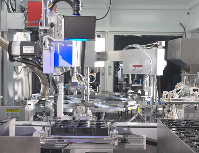
A custom liquid cold plate is a metal heat exchanger designed to absorb heat from one or more components and transfer it to a circulating coolant. The plate normally contains internal channels, drilled passages, vacuum-brazed layers, machined grooves, or friction-stir-welded structures.
The heat path is usually:
Engineers often describe cold plate performance through several technical terms:
The basic heat-load relationship is:
Q = m × Cp × ΔT
Here, Q is heat load in watts, m is coolant mass flow rate, Cp is the specific heat capacity of the coolant, and ΔT is the coolant temperature increase. This equation helps an engineer estimate the coolant flow needed for a target heat load.
Air cooling becomes difficult when heat is concentrated in a small area. A fan and heatsink may require more space, create acoustic noise, and struggle with high heat flux. Liquid cooling places the heat-transfer surface close to the heat source and can carry heat away through narrow channels.
The U.S. Department of Energy has reported that data-center cooling can represent a significant share of facility energy use, with cooling requirements varying by equipment load and system design. The American Society of Heating, Refrigerating and Air-Conditioning Engineers, commonly known as ASHRAE, also publishes guidance for thermal management in data centers and electronic equipment. These sources show why cooling design must consider both component temperature and total system energy use.
For a battery system, temperature uniformity is also important. Uneven cooling can create different cell temperatures, which may affect battery aging and electrical performance. A cold plate with balanced channels can help reduce temperature differences across the battery module.
A manufacturer cannot select the best channel design from the outside dimensions alone. Accurate design requires thermal, mechanical, fluid, electrical, and production information.
Provide the following data:
For example, a 2,000 W application with a coolant temperature rise limited to 5°C requires a different flow rate from a 2,000 W system that allows a 15°C rise. The thermal target should be defined before channel dimensions are selected.
Send a 2D drawing, 3D CAD model, or clear technical sketch that includes:
Mounting pressure matters. Excessive pressure can damage a semiconductor package or battery module, while insufficient pressure can increase thermal contact resistance. The cold plate should match the mounting system, gasket design, and torque limits.
State the exact coolant whenever possible. Common choices include deionized water, water-glycol mixtures, dielectric fluids, and engineered coolants. The manufacturer needs to know:
Water has high heat capacity and low viscosity compared with many engineered fluids, but it can increase corrosion risk if the material and coolant chemistry are not controlled. Water-glycol coolant can provide freeze protection, but its viscosity and heat-transfer performance change with concentration and temperature.
Common cold plate materials include:
Specify the alloy, coating, anodizing, plating, or passivation requirement. If the cold plate will contact aluminum tubing, copper fittings, or stainless-steel components, ask for a galvanic corrosion review.
CNC machining creates channels, pockets, mounting holes, and ports from a solid metal plate. It is useful for prototypes, low-volume production, and designs that need accurate external features.
Advantages:
Limitations: Deep or narrow channels may increase machining time. Internal passages may also require a cover plate, plug, or welded closure.
Vacuum brazing joins a base plate and cover plate with a filler metal inside a controlled furnace. It can create sealed internal channels with a clean external surface.
This method is useful for medium- and high-volume applications that need consistent channel geometry. The brazing cycle must be controlled to prevent distortion, blocked passages, or incomplete joints.
Friction stir welding joins metal components through heat and mechanical pressure without melting the main material in the same way as conventional fusion welding. It is often considered for larger aluminum cold plates and battery cooling panels.
The process can produce strong sealed joints, but the design must provide a suitable weld path and enough material around the channel area.
Extrusion and stamping can reduce unit cost for repeat production. These processes work best when the cross-section or geometry remains consistent across many units. Additional machining, sealing, or welding may still be required for ports and end closures.
Metal additive manufacturing can create complex channel networks, compact manifolds, and internal structures that are difficult to produce with standard machining. It may be suitable for prototypes, aerospace equipment, and specialized high-heat-flux systems.
However, engineers should review surface roughness, powder removal, leak testing, material properties, production cost, and long-term reliability before selecting this route.
A capable supplier should support more than metal cutting. Review the following points before placing an order.
Ask whether the supplier can perform thermal calculations, computational fluid dynamics analysis, or thermal testing. The design review should examine heat distribution, channel balance, local hot spots, coolant velocity, and pressure drop.
Confirm whether the supplier can provide:
A cold plate with an internal leak can damage expensive electronics. Ask for the test medium, pressure, holding time, detection limit, and test report format. Typical tests may include air-under-water testing, pressure decay testing, helium leak testing, or hydrostatic testing, depending on the application.
The test pressure must be agreed before production. It should reflect the maximum operating pressure and the safety factor required by the system specification.
Important documents may include:
ISO 9001 certification can indicate that a supplier operates a documented quality management system. It does not, by itself, prove that a specific cold plate will meet your thermal target, so product-level testing remains necessary.
Set the maximum component temperature, heat load, coolant temperature, flow rate, pressure limit, and expected service life. Avoid using unclear terms such as “high performance” or “fast cooling.” Use measurable limits such as “remove 3,000 W while keeping the device base below 75°C.”
Check the complete assembly, not only the cold plate. The pump, tubing, fittings, radiator, insulation, sensors, and service clearance can affect the final design.
Channel layout affects heat transfer and pumping power. Straight channels can reduce pressure drop and simplify manufacturing. Serpentine channels can increase coolant contact length but may create a higher pressure drop. Parallel channels can improve area coverage, but poor manifold design may cause uneven flow.
The supplier should estimate cold plate thermal resistance, coolant temperature rise, flow distribution, and pressure drop. For critical equipment, test data should support the model.
Check dimensions, port sealing, surface flatness, mounting compatibility, flow direction, and thermal contact. Test the prototype under both normal and worst-case conditions.
Depending on the application, testing may include:
Before production approval, freeze the drawing revision, inspection plan, material specification, test limits, packaging method, and accepted sample. A formal approval process helps prevent an unapproved change from affecting thermal or leak performance.
Battery cold plates remove heat from cells, modules, or busbar regions. They can also support temperature balancing during charging and discharging. The design must account for vibration, coolant leakage risk, pack sealing, electrical isolation, and service conditions.
Servers, AI accelerators, inverters, rectifiers, and power-conversion systems may use direct-to-chip or component-level liquid cooling. The cold plate must match the processor package, mounting frame, manifold, and facility coolant loop.
Laser diodes and optical systems can require stable operating temperatures because wavelength, beam quality, and output power may shift with temperature. A cold plate can provide more controlled heat removal than a standard heatsink.
Imaging systems, high-power diagnostic devices, and laboratory instruments may need compact cooling with controlled noise and vibration. Materials, cleanliness, fluid compatibility, and regulatory documentation should be reviewed early.
Motors, servo drives, welding systems, plasma equipment, and semiconductor tools can generate concentrated heat. Custom plates help engineers use the available mounting area instead of adding a larger external heatsink.
These systems often require low weight, high reliability, controlled fluid paths, and resistance to vibration and temperature changes. Design verification and traceable documentation are usually more demanding than in general industrial equipment.
These benefits should be verified through measurements. A useful test report should show heat load, coolant inlet temperature, flow rate, pressure drop, component temperature, outlet temperature, and test uncertainty.
Two systems may have the same total wattage but different hot-spot locations. Channel design should consider the highest local heat flux, not only the average heat load.
A channel may provide strong heat transfer but require more pump pressure than the system can deliver. Always compare the cold plate pressure-drop curve with the pump performance curve.
Mixed-metal coolant loops can create galvanic corrosion. Review material pairing, coolant inhibitors, electrical conductivity, and operating temperature before selecting copper, aluminum, or stainless steel.
Ports need tool clearance, and seals need a suitable compression range. Include access for leak testing, tube replacement, and drain or fill operations.
Viscosity, pressure, material expansion, and sealing behavior can change with temperature. Validate the cold plate across the expected operating range.
There is no single best coolant. Water offers high heat capacity, while water-glycol mixtures add freeze protection. Dielectric fluids may be used when electrical isolation is important. The choice depends on heat load, temperature range, corrosion risk, pump capacity, and component safety.
Use the relationship Q = m × Cp × ΔT. Divide the heat load by the coolant specific heat capacity and the allowed temperature rise to estimate the required mass flow. Convert mass flow to volume flow using the coolant density. A supplier should then verify the result with pressure-drop and flow-distribution analysis.
Copper generally provides higher thermal conductivity, while aluminum offers lower weight and often lower material cost. The correct choice depends on thermal resistance, weight, corrosion control, joining method, and budget.
Yes. Battery cold plates are used in electric vehicles, energy-storage systems, test equipment, and industrial battery modules. The design must address cell spacing, electrical isolation, vibration, coolant leakage, pack sealing, and temperature uniformity.
Common methods include pressure decay, air-under-water, hydrostatic, and helium leak testing. The correct method depends on the internal volume, pressure rating, coolant, required sensitivity, and product standard.
Send a 3D CAD file, 2D drawing, heat-load map, coolant specification, flow and pressure limits, mounting details, material requirements, surface treatment requirements, annual volume, and required inspection documents.
The schedule depends on design complexity, material availability, tooling, testing, and order volume. A simple machined prototype may move faster than a brazed or welded production design. Request a stage-by-stage schedule covering design review, prototype, testing, revisions, and production approval.
When your application requires a custom liquid cooling solution, begin with measurable requirements rather than a standard catalog size. Prepare the heat load, temperature limits, CAD drawing, coolant data, flow target, pressure limit, material preference, and testing requirements. Then ask the supplier to confirm thermal performance, manufacturability, leak resistance, and documentation.
Onlink can be considered for projects that need custom liquid cold plates, battery cooling plates, and other thermal management components. Contact the team with your design information and request an engineering review, prototype plan, and test proposal. For readers comparing a bespoke thermal cooling parts supplier, the next useful step is to review the user guide, prepare a complete design brief, and request a sample evaluation from Onlink.


