Nov.16,2026
Insert Overmolding Services combine a metal or plastic insert with injection-molded polymer in one finished part. This process can reduce assembly steps, protect electrical contacts, and improve grip and sealing. For companies comparing custom insert overmolding services, the key questions are usually practical: What tolerance is possible? Which material should be used? How can the insert stay in the correct position during molding? This guide explains the full process, from design and tooling to inspection and production, so you can choose a reliable solution for your product.
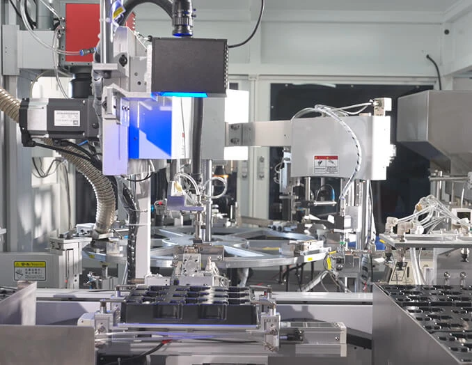
Insert overmolding is an injection molding process in which a preformed insert is placed inside a mold. Molten thermoplastic is then injected around part of the insert. After cooling, the insert and plastic become one component.
The insert may be made from:
The technical term insert means the component placed into the mold before plastic injection. Overmolding means forming a second material around an existing component. When the insert carries electrical current, the process may also be called insert molding, terminal overmolding, or electrical connector overmolding.
Unlike a simple plastic housing, an insert-overmolded part performs several functions at the same time. The plastic can provide insulation, impact protection, strain relief, sealing, and a finished grip. The insert can provide conductivity, strength, threads, a mounting point, or wear resistance.
The achievable tolerance depends on the plastic material, part size, insert design, mold construction, machine stability, and inspection method. It is not accurate to assign one tolerance value to every overmolded part.
In many production projects, general molded dimensions may be controlled around ±0.10 mm to ±0.30 mm for selected features and part sizes. Larger dimensions, flexible materials, deep cavities, and long flow paths may require wider limits. Critical insert locations can often be controlled more tightly through precision tooling and dedicated fixtures, but the final value must be confirmed by a design-for-manufacturing review.
Commonly controlled dimensions include:
| Feature | Typical control method | Why it matters |
|---|---|---|
| Insert position | Precision mold nests, pins, and loading fixtures | Controls alignment with holes, contacts, and mating parts |
| Plastic wall thickness | Core and cavity dimensions, flow analysis | Reduces sink marks, warpage, and uneven cooling |
| Overall length and width | Cavity machining and process inspection | Supports assembly fit and packaging requirements |
| Thread location | Fixed threaded insert or metal core | Prevents cross-threading and mounting errors |
| Flash at the insert interface | Mold shutoff design and clamp control | Protects appearance and prevents interference during assembly |
ISO 2768 provides general tolerances for parts where individual tolerances are not specified. However, injection-molded plastic parts also change size because of material shrinkage, mold temperature, packing pressure, fiber orientation, and cooling conditions. For this reason, critical dimensions should receive individual tolerances on the drawing rather than relying only on a general tolerance standard.
For a metal insert overmolding project, the drawing should identify:
Useful standards and technical references include for general dimensional tolerances, for plastics molding tolerances, and injection molding design guidance from . These references help establish a starting point, but the final tolerance should be validated with the actual material and tool.
The process starts with the product function. The manufacturer should understand the load, temperature, chemical exposure, electrical voltage, sealing requirement, and expected service life.
For example, a connector used near engine heat needs a different resin and insert surface treatment than a low-voltage indoor cable strain relief. A threaded insert that receives repeated tightening also needs stronger mechanical retention than a decorative metal plate.
The insert material should match the required strength, conductivity, corrosion resistance, and cost. Brass is common for electrical terminals because it offers useful conductivity and machinability. Stainless steel is selected when corrosion resistance and strength are more important.
Common overmolding plastics include:
Material selection should consider the melt temperature of the plastic and the heat resistance of the insert, coating, adhesive, or electronic component. The resin supplier’s technical data sheet should be used for tensile strength, heat deflection temperature, shrinkage, chemical resistance, and processing conditions.
A smooth insert can move during injection. Good designs add mechanical features that allow the polymer to lock around the insert.
Useful retention features include:
Mechanical retention is usually more dependable than relying only on chemical adhesion. However, the insert should not contain sharp edges that create thin plastic sections or stress concentrations. The transition between thick and thin areas should be designed carefully to limit sink marks and warpage.
The mold must hold the insert in a repeatable position during closing and injection. Depending on the part, the tool may use locating pins, nests, slides, magnets, vacuum retention, or automatic loading equipment.
The mold designer also checks:
Poor venting can create burn marks, short shots, or weak weld lines. Incorrect gate placement can push the insert out of position. A mold-flow study can help identify these risks before tool production, especially for large parts or complex insert layouts.
The insert can be loaded by an operator or by an automated system. Manual loading may suit lower production volumes and frequent design changes. Automation can improve cycle consistency when the same insert is used in large quantities.
Before molding, inserts should be clean and free from oil, metal chips, loose plating, and moisture. For some engineering plastics, preheating the insert may improve bonding and reduce thermal shock. The correct method depends on the insert material, plastic resin, and production specification.
During injection, molten plastic flows around the insert. The machine controls injection speed, pressure, temperature, holding pressure, and cooling time. These settings affect shrinkage, insert movement, voids, flash, and surface quality.
Cooling is especially important because plastic contracts as it changes from a molten state to a solid state. Different cooling rates around a metal insert can create uneven stress. A balanced wall thickness and well-designed cooling system can reduce distortion.
After cooling, the mold opens and the finished part is ejected. Inspection may include visual checks, dimensional measurement, electrical testing, leak testing, pull-out testing, and torque testing.
For a connector, inspection may verify contact position, dielectric strength, and continuity. For a threaded insert, testing may measure torque resistance and pull-out force. For a sealed sensor housing, the manufacturer may use an air-pressure decay test or another agreed leak-test method.
Insert overmolding is used for sensor connectors, cable guides, battery components, switch parts, mounting brackets, and electrical terminals. The plastic layer can protect metal components from vibration, moisture, road salt, and accidental contact.
Automotive projects usually require detailed validation because parts may face temperature changes, vibration, fluid exposure, and long service periods. Material selection should follow the required automotive specification and any customer-specific test plan.
Electrical insert molding protects terminals, pins, busbars, and wire connections. It can reduce the number of separate housing and assembly operations while improving insulation and strain relief.
Important requirements may include:
Medical devices may use overmolded metal parts in handles, diagnostic equipment, connectors, and fluid-control components. The design may need biocompatible materials, clean manufacturing, traceability, and controlled packaging.
Not every medical part can use a standard molding process. The resin, cleaning method, sterilization method, and production environment must be reviewed before tooling begins.
Consumer products use insert overmolding for tool handles, charging connectors, switches, wearable components, and protective grips. A soft elastomer can be molded over a rigid frame to improve handling without adding a separate assembly step.
Industrial applications include control panels, cable glands, sensors, power equipment, and machine components. Overmolding can protect the insert from impact and help create a sealed or insulated assembly.
A molded plastic housing can replace several separate parts, such as a cover, adhesive layer, strain-relief boot, and retaining clip. The exact reduction depends on the product design, but removing one manual assembly step can reduce handling time and lower the chance of assembly error.
The polymer surrounds the insert and protects it from impact, contamination, and accidental contact. In electrical products, the plastic may also provide insulation and controlled spacing between conductive elements.
Knurls, holes, grooves, and shoulders allow the plastic to lock around the insert. This can improve resistance to rotation and pull-out compared with a smooth press-fit insert.
When the mold and process are stable, the plastic surface can provide a repeatable shape and finish. This is useful for consumer products where visible seams, flash, and parting lines must be controlled.
Tooling investment is higher than for a simple one-off assembly, but the unit cost can fall at medium and high volumes. A proper cost comparison should include material, molding cycle time, insert loading, secondary assembly, inspection, scrap, and maintenance.
Cause: The insert is not firmly supported, or injection pressure pushes it away from the intended position.
Prevention: Use locating features, stronger mold nests, mechanical locks, lower initial injection speed, or a revised gate location. Measure the insert position after molding rather than checking only the outer plastic shape.
Cause: The mold shutoff is not sealing correctly, the insert size varies, or clamp force is insufficient.
Prevention: Improve shutoff geometry, control insert dimensions, remove debris from the mold, and confirm the correct machine clamp force. Flash limits should be stated on the drawing.
Cause: The plastic does not fill the cavity before freezing. Low melt temperature, restricted flow, poor venting, or an undersized gate may be involved.
Prevention: Review gate size, venting, injection speed, melt temperature, and material drying requirements.
Cause: Air is trapped around the insert, or the plastic shrinks away from a thick section.
Prevention: Add vents, change the gate position, balance wall thickness, and optimize holding pressure. X-ray or ultrasonic inspection may be needed for hidden voids in critical products.
Cause: The plastic does not chemically adhere to the insert, or the insert surface is contaminated.
Prevention: Clean and prepare the insert surface, use a compatible material pair, add mechanical retention, and test the finished part under the actual service load.
Cause: Uneven cooling, material shrinkage, fiber orientation, or unbalanced wall thickness.
Prevention: Use uniform wall sections, improve cooling balance, adjust packing conditions, and define the measurement time after molding. Some parts should be inspected after a controlled conditioning period because moisture absorption can change the dimensions of materials such as nylon.
A clear project brief helps the manufacturer give an accurate design and production recommendation. Include the following information:
Ask for a design-for-manufacturing report before approving the tool. The report should identify draft angles, wall thickness, gate position, ejection, insert retention, tolerance risks, and possible cosmetic defects.
Do not compare suppliers only by piece price. Review their ability to control the complete process.
For high-volume parts, ask how the supplier measures process stability. A useful quality program may include first-article inspection, control plans, capability studies, gauge repeatability and reproducibility, and regular tool maintenance.
Onlink can be considered for projects that require metal insert overmolding, custom plastic components, electrical protection, or integrated assembly support. When contacting Onlink, provide the drawing, insert sample or specification, resin requirement, target volume, and critical test values. This allows the engineering team to review feasibility instead of giving a price based on incomplete information.
The final cost depends on more than the amount of plastic in the part. The main cost drivers include:
A single-cavity mold may be suitable for prototypes or low annual demand. Multi-cavity tooling can reduce the molding cycle cost per piece, but it requires higher initial investment and tighter cavity-to-cavity balancing.
Lead time is affected by design approval, insert sourcing, mold construction, first-shot trials, sample inspection, and engineering changes. A project with a complete CAD package and stable material specification usually moves through review faster than a project with unclear tolerances and several pending design changes.
No. The plastic must have a suitable processing temperature, shrinkage behavior, and bonding or mechanical-retention method. The insert coating, plating, adhesive, and electronic content must also tolerate the molding process.
It can provide strong mechanical retention when the insert uses grooves, knurls, holes, or shoulders. However, strength depends on geometry, resin, temperature, load direction, and processing quality. Pull-out and torque tests should be completed on representative samples.
Usually, it is the position of the insert relative to the mating or functional features. A small shift may cause a connector to misalign, a screw to bind, or an electrical contact to fail. Mark this requirement as critical on the drawing.
It can support a sealed design, but overmolding alone does not guarantee a waterproof rating. The part needs suitable material, wall thickness, shutoffs, interfaces, and validation testing. Define the required IP rating or leak-test limit before tool design.
Yes. Threaded inserts are commonly used for mounting and repeated assembly. The mold must protect the thread, maintain the correct orientation, and provide enough surrounding plastic to resist pull-out and rotation.
Yes, although the tooling method may differ from mass production. Prototype molds, soft tools, or manual insert loading can be used to test fit, material, retention, and appearance before investing in a high-cavity production tool.
Start with controlled insert dimensions and a stable locating fixture. Then review the mold shutoff, gate position, venting, clamp force, and injection profile. Inspect both the insert position and the outer plastic dimensions during the pilot run.
Send a 3D CAD model, 2D drawing, insert specification, plastic or resin requirement, expected quantity, color, surface finish, and required tests. If the design is still under development, include the main function and known tolerance concerns so Onlink can suggest a practical design direction.
Begin by identifying the part’s load, environment, material, and critical dimensions. Then prepare the CAD files and mark the insert position, sealing areas, cosmetic surfaces, and required tests. Request a design-for-manufacturing review before approving the mold. During sampling, check dimensions, insert retention, appearance, electrical performance, and any leak or environmental requirements.
For companies looking for a precision insert molding manufacturer, the best next step is to send the complete project information to Onlink for an engineering review. A well-defined tolerance plan and test method can prevent tool changes, reduce scrap, and create a more stable production process.


