
When a vehicle prototype suffers from intermittent sensor faults, overloaded circuits, difficult assembly, or connectors that do not fit the packaging envelope, the wiring harness is often the hidden cause. This guide is written for automotive engineers, purchasing teams, startup vehicle developers, and manufacturing managers who need a reliable automotive wiring harness design guide, a practical Custom Automotive Wiring Harness Manufacturer, or a controlled path for automotive wiring harness prototype to production. It explains wire gauge selection, connector pinout, and circuit protection, while connecting them to professional practices such as crimp force monitoring, ISO 26262, and IPC/WHMA-A-620.
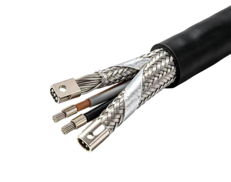
Why a Custom Automotive Wiring Harness Manufacturer Should Join the Design Process Early
A harness is not simply a bundle of wires. It is an electromechanical system that carries power and data, controls electromagnetic compatibility, protects circuits, supports service access, and determines how efficiently technicians can build the vehicle. A schematic may show logical connections, but production requires physical routing, bend radii, cavity seals, terminal retention, branch locations, clipping points, and inspection features.
Late harness changes are expensive because one small change can affect several linked items:
- A new 12 V actuator may require a larger conductor, a different fuse rating, and a larger terminal.
- A revised ECU location may add 400 mm of cable, increasing voltage drop and electromagnetic exposure.
- A connector moved by 20 mm may force a new branch length, tape wrap, clip position, and enclosure interface.
- A high-voltage battery circuit may require orange insulation, interlock monitoring, shielding, touch-safe connectors, and a defined creepage and clearance design.
Onlink approaches harness development as a controlled engineering process rather than a final assembly task. The practical goal is to freeze electrical intent early, validate the physical design against the vehicle, and release manufacturing documents that a production operator can follow without interpretation.
Automotive Wiring Harness Design Guide: Basic Terms and Electrical Principles
Custom Automotive Wiring Harness Manufacturer Terminology for New Designers
- Wire harness
- An organized assembly of wires, terminals, connectors, seals, splices, protective coverings, clips, labels, and related components.
- Branch
- A section that separates from the main trunk to serve a sensor, actuator, lighting module, ECU, or power distribution point.
- Cavity
- A numbered position inside a connector housing. Cavity numbering must be controlled because an incorrect terminal location can create a short circuit or reverse signal polarity.
- Splice
- An electrically and mechanically joined connection between two or more conductors. Splices require defined tooling, crimp geometry, insulation support, sealing, and inspection criteria.
- Terminal
- The metallic contact crimped or welded to a conductor and inserted into a connector housing, fuse block, relay base, or grounding point.
- Breakout
- The point where a branch leaves a trunk. Breakout position affects assembly sequence, bend stress, installation time, and serviceability.
Wire Gauge Selection in a Custom Automotive Wiring Harness
Conductor selection should begin with current, length, allowable voltage drop, ambient temperature, bundling, insulation rating, and installation environment. A common first calculation is:
Voltage drop = current × resistance
For a two-wire 12 V circuit, the resistance path includes the outgoing and return conductors. For example, if a 5 A load uses a 3 m total copper path and the conductor resistance is 0.013 Ω/m, the estimated voltage drop is:
5 A × 3 m × 0.013 Ω/m = 0.195 V
That result is approximately 1.6% of a 12 V nominal supply. The designer must then account for connector resistance, fuse contacts, splice resistance, temperature rise, and the vehicle’s low-voltage operating condition. A circuit that works at 14.2 V during alternator charging may behave differently when the battery voltage falls near 10.5–11 V during engine cranking.
Do not select a conductor only by its ampacity table. A 0.35 mm² conductor may carry a low-current sensor signal, while a motor circuit may require 2.5 mm², 4 mm², or a larger cross-section depending on duty cycle and thermal conditions. Automotive wire families such as TXL, GXL, SXL, FLRY, and high-voltage shielded cable have different insulation thicknesses, temperature ratings, flexibility, and chemical resistance.
Connector Pinout and Circuit Protection for Automotive Harnesses
A connector pinout should identify cavity number, circuit name, signal direction, wire color, wire size, terminal part number, sealing method, and mating connector. A spreadsheet with only wire color and destination is not sufficient for production control.
Every powered branch should have a defined protective device. Fuse selection must consider:
- Normal operating current and inrush current.
- Continuous-load duration and ambient temperature.
- Wire ampacity under the actual bundle arrangement.
- Fuse opening characteristics and short-circuit current.
- Load behavior during cold crank, motor stall, and inductive switching.
For inductive loads such as solenoids, relays, and motors, suppression may be required to control voltage transients. A flyback diode, transient-voltage suppressor, resistor-capacitor network, or ECU-integrated protection can reduce stress on switching devices. The solution must match the polarity, switching frequency, release-time requirement, and diagnostic strategy of the circuit.
Custom Automotive Wiring Harness Manufacturer Workflow: From Schematic to Design Release
Step 1: Convert the Vehicle Schematic into a Harness Requirements List
- Collect electrical inputs. Gather schematics, ECU interface documents, load lists, fuse maps, communication requirements, grounding plans, and diagnostic specifications.
- Identify every endpoint. Record each sensor, actuator, battery connection, control module, lighting unit, motor, switch, and grounding stud.
- Classify circuit behavior. Separate power, ground, analog, digital, PWM, CAN, LIN, Ethernet, audio, high-voltage, and safety-related circuits.
- Define environmental exposure. Note engine-bay temperature, water splash, salt spray, oil exposure, vibration, abrasion, flexing, and chemical contact.
- Assign design ownership. Clarify which party controls connector selection, terminal approval, fuse strategy, EMC targets, software pin assignment, and change approval.
The output should be a requirements matrix with a unique circuit ID. This ID must remain consistent across the schematic, wire list, 2D drawing, 3D routing model, test plan, and end-of-line tester.
Step 2: Select Wires, Terminals, Connectors, and Protective Materials
- Select the conductor. Choose cross-section, insulation family, color, stripe, temperature rating, flexibility, and minimum bend radius.
- Match the terminal to the conductor. The terminal’s conductor range, insulation support, plating, contact force, and sealing design must match the wire and environment.
- Check connector capacity. Confirm current rating by cavity, maximum voltage, temperature derating, keying, CPA or TPA features, ingress protection, and mating-cycle requirement.
- Choose protection. Use convoluted tubing, braided sleeving, fabric tape, PVC tape, heat-shrink tubing, aluminum shielding, grommets, or abrasion-resistant conduit according to the installation zone.
- Control part substitutions. An apparently equivalent connector may have different terminal plating, cavity geometry, sealing performance, or retention force. Substitution requires engineering approval and validation.
For signal integrity, keep CAN and other high-speed differential pairs twisted according to the transceiver and cable requirements. Avoid unnecessary parallel routing beside high-current motor or inverter conductors. Use shield termination and grounding methods that are consistent with the vehicle’s EMC architecture; a shield connected incorrectly at multiple points can create an unintended ground-current path.
Step 3: Create the Physical Layout with a Custom Automotive Wiring Harness Manufacturer
- Start with the vehicle coordinate system. Import mounting points, body panels, battery locations, ECUs, engines, doors, seats, and service zones into the 3D environment.
- Route the main trunk. Keep the path away from exhaust heat, sharp edges, moving mechanisms, and water collection areas.
- Place branches by installation sequence. A branch should reach its connector without forcing the operator to twist or stretch the harness.
- Set bend radii. Follow the minimum bend radius specified by the wire, shield, conduit, and connector manufacturer. High-voltage cable and shielded data cable generally require more controlled routing than ordinary low-voltage wire.
- Add clips and retainers. Position them to prevent contact with moving parts and to control vibration. Avoid placing a clip directly on a breakout unless the design specifically supports it.
- Check service loops. Provide enough slack for connector mating, module removal, door movement, seat adjustment, or battery service without allowing the cable to rub or hang.
A useful review combines digital clearance analysis with a physical buck or vehicle trial. A 3D model can reveal a collision, but it may not show how a technician’s hand enters a confined connector area or how a wrapped bundle behaves during installation.
Step 4: Produce Harness Drawings, Wire Lists, and Manufacturing Data
- Release the wire list. Include circuit ID, wire part number, color, cross-section, cut length, from-cavity, to-cavity, terminal, seal, splice, and processing notes.
- Release the 2D harness drawing. Show connector orientation, branch lengths, breakout dimensions, tape starts and stops, tube lengths, clips, labels, and inspection dimensions.
- Define terminal processing. Specify strip length, conductor crimp height, insulation crimp height, bellmouth, cut-off tab, wire brush, and pull-force requirements according to the approved terminal specification.
- Create the bill of materials. Link every component to an approved part number, revision, supplier, and quantity per assembly.
- Build the test program. Include continuity, short-to-ground, short-to-battery, miswire, resistance, insulation, and high-voltage withstand tests where applicable.
Manufacturing documents should use revision-controlled identifiers. If the design changes from a two-cavity connector to a four-cavity connector, the change must update the drawing, bill of materials, wire list, tester program, work instructions, and inspection plan together.
Automotive Wiring Harness Prototype to Production: Tools, Testing, and Quality Gates
Prototype Tools Used by a Custom Automotive Wiring Harness Manufacturer
- Electrical CAD or harness design software for schematics, wire lists, and connector databases.
- 3D CAD software for routing, clearance, bracket placement, and installation analysis.
- Digital calipers, pin gauges, wire micrometers, and go/no-go gauges for dimensional control.
- Crimp-height micrometers and terminal cross-section microscopes for process verification.
- Crimp force analyzers for detecting incomplete crimps, over-crimps, conductor loss, or insulation-support defects.
- Low-resistance ohmmeters for splice and terminal resistance measurements.
- Harness testers for continuity, short detection, component presence, and cavity verification.
- Insulation resistance and hipot equipment for high-voltage systems.
- Oscilloscopes and CAN/LIN analyzers for signal quality, termination, bus errors, and transient behavior.
Step 5: Build and Inspect the Prototype Harness
- Cut and mark wires. Verify cut length and identification before terminal processing. For a long production harness, automatic cut-and-strip equipment reduces variation, but the recipe must be locked to the approved wire part number.
- Crimp terminals. Confirm applicator setup, terminal orientation, strip length, crimp height, conductor brush, insulation support, and pull force.
- Perform cross-section analysis. A cross-section can expose insufficient conductor compression, cracked wings, excessive flash, voids, or misplaced insulation support.
- Assemble connectors. Confirm cavity position, terminal lock, secondary lock, seal placement, and connector keying.
- Apply protection and labels. Control tape overlap, tubing position, braid termination, grommet seating, branch dimensions, and label readability.
- Run electrical tests. Test continuity and isolation before the harness is installed in the vehicle or test fixture.
Crimp quality should be evaluated with measured data rather than visual confidence. For example, a production control plan may require a defined crimp-height window, terminal pull-force minimum, and cross-section approval for each terminal-wire combination. The exact limits must come from the terminal manufacturer, vehicle customer, or applicable process specification rather than a generic value.
Step 6: Validate Electrical, Mechanical, Environmental, and EMC Performance
- Electrical validation. Measure circuit resistance, voltage drop under load, insulation resistance, dielectric withstand where required, and fuse coordination.
- Mechanical validation. Check connector retention, terminal retention, pull-out behavior, clip retention, bundle compression, flex life, and installation force.
- Environmental validation. Use temperature cycling, humidity exposure, water ingress, salt spray, chemical exposure, vibration, abrasion, and thermal aging according to the vehicle program requirements.
- EMC validation. Evaluate radiated emissions, conducted emissions, susceptibility, CAN communication stability, shield continuity, and grounding performance.
- Safety validation. Apply the project’s functional-safety analysis, diagnostic coverage, electrical separation, and failure-mode controls. ISO 26262 is relevant when the harness supports safety-related functions, but the required Automotive Safety Integrity Level depends on the hazard analysis.
For a practical example, consider a 12 V cooling-fan harness carrying 18 A over a 4 m round-trip path. If the selected wire produces 0.18 Ω total resistance at the operating temperature, the cable alone dissipates:
P = I²R = 18² × 0.18 = 58.32 W
That heat may be unacceptable inside a tightly bundled engine compartment, even if the circuit appears functional during a short bench test. Reducing resistance to 0.08 Ω lowers cable dissipation to approximately 25.92 W and reduces voltage drop from 3.24 V to 1.44 V. The final decision still requires thermal testing, fuse coordination, connector rating review, and packaging analysis.
Custom Automotive Wiring Harness Manufacturer Production Controls
Step 7: Prepare the Production Line and Work Instructions
- Define the process sequence. Typical operations include wire cutting, stripping, terminal crimping, splice processing, subassembly, connector insertion, taping, tubing, labeling, and final testing.
- Use poka-yoke controls. Fixtures, cavity boards, barcode scanning, connector key checks, and digital wire-list verification reduce misrouting and wrong-part insertion.
- Set first-piece approval. The first completed harness after a setup, tool change, material change, or revision change should receive documented dimensional and electrical approval.
- Monitor critical processes. Track crimp force signatures, crimp height, pull force, cut length, resistance, test failures, and rework frequency.
- Control operator instructions. Work instructions should show connector orientation, terminal insertion direction, tape overlap, branch dimensions, and inspection points with photographs or diagrams.
IPC/WHMA-A-620 is commonly used as a workmanship reference for cable and wire harness assemblies. It does not replace customer drawings or vehicle-specific specifications, but it provides a structured basis for evaluating soldering, crimping, insulation, marking, and mechanical workmanship.
Step 8: Manage Traceability and Engineering Changes
- Assign lot traceability. Record wire, terminal, seal, connector, tape, and protective material lots for each production batch.
- Track tester results. Store the harness serial number, test date, operator, tester program revision, failure code, and repair status.
- Use formal change notices. Each engineering change should identify the reason, affected parts, risk assessment, validation requirement, and implementation date.
- Protect obsolete stock. Separate old and new revisions physically and electronically to prevent mixed assemblies.
- Review field feedback. Warranty returns, installation complaints, connector damage, and intermittent faults should feed back into the design and process FMEA.
Traceability is especially important for battery, airbag, braking, steering, and driver-assistance harnesses. A production record that links the finished harness to its material lots and test results can reduce diagnostic time when a field issue appears months after vehicle assembly.
Advanced Automotive Wiring Harness Design Techniques
Weight Reduction by Circuit and Material Analysis
Harness mass can be reduced without compromising reliability by evaluating each circuit rather than reducing every wire indiscriminately. Multiplexing can replace multiple discrete control wires with a communication network, while local power distribution can shorten high-current paths. However, network design adds requirements for termination, diagnostics, wake-up behavior, shielding, software integration, and failure-mode analysis.
Useful weight-reduction methods include:
- Replacing unnecessary discrete signal lines with validated CAN or LIN communication.
- Moving a fuse or power distribution point closer to high-current loads.
- Reducing excessive service-loop length after installation trials.
- Using thin-wall wire where the electrical, thermal, mechanical, and terminal requirements permit it.
- Optimizing tape, conduit, and shielding coverage according to measured abrasion and EMC risks.
EMC and High-Speed Data Design for Custom Automotive Harnesses
For CAN networks, the nominal bus topology, termination resistance, stub length, common-mode behavior, and pair routing must be controlled. A typical high-speed CAN network uses 120 Ω termination at each physical end, producing approximately 60 Ω when measured across the powered-off bus if both terminators are present. The actual vehicle architecture may differ, so the approved network specification takes priority.
Keep high-speed pairs away from rapidly switching power cables, inverter outputs, ignition systems, and motor conductors where practical. Avoid sharp untwisting near terminals, uncontrolled shield pigtails, and long unshielded transitions. Validate the assembled harness in the vehicle because body structure, grounding points, and neighboring modules can change the measured EMC result.
High-Voltage Harness Design and Safety Separation
High-voltage battery and inverter harnesses require more than a larger wire. The design may include orange insulation, HVIL interlock circuits, touch-safe terminals, shielding, connector CPA and TPA systems, creepage and clearance evaluation, insulation resistance testing, and controlled service procedures.
The design review should define:
- Nominal voltage, maximum operating voltage, and transient voltage.
- Continuous and peak current, including regenerative or charging conditions.
- Shield termination strategy and enclosure bonding.
- Minimum bend radius and flex-life requirements.
- Isolation monitoring and diagnostic thresholds.
- Connector touch protection and accidental-mating prevention.
- Lockout, tagout, and end-of-line test procedures.
How to Evaluate a Custom Automotive Wiring Harness Manufacturer
Before awarding a program, ask for evidence rather than general capability statements. A suitable supplier should be able to explain its process for:
- Electrical schematic interpretation and wire-list generation.
- 3D routing and physical packaging review.
- Terminal application engineering and crimp validation.
- Connector, seal, splice, and protective-material selection.
- Prototype builds and vehicle installation support.
- Continuity, isolation, hipot, resistance, and communication testing.
- Process FMEA, control plans, work instructions, and change management.
- Material traceability and production data retention.
- Support for low-volume prototypes, pilot runs, and repeat production.
Request a sample drawing package and confirm whether it includes cavity tables, cut lengths, branch dimensions, terminal part numbers, inspection criteria, tester data, and revision history. Also verify whether the manufacturer can work with the connectors and terminals already approved by the vehicle program or can support a documented component-approval process.
Practical Automotive Wiring Harness Design Review Checklist
- Does every circuit have a unique identifier from schematic through final test?
- Are wire size, insulation type, temperature rating, and current limits documented?
- Has voltage drop been calculated at the worst-case supply voltage and operating temperature?
- Are fuses and protective devices coordinated with wire ampacity and inrush current?
- Are connector cavities, terminal families, seals, and secondary locks verified?
- Are branch lengths, bend radii, clips, grommets, and service loops defined?
- Is the harness protected from heat, abrasion, water, oil, vibration, and moving parts?
- Are CAN, LIN, Ethernet, shielded, and high-voltage circuits routed according to their signal requirements?
- Have crimp height, pull force, cross-section, and crimp-force signatures been validated?
- Does the tester detect open circuits, short circuits, wrong cavities, missing components, and incorrect resistance?
- Are prototype and production revisions separated through formal change control?
- Can the finished harness be installed without excessive force, twisting, or connector access problems?
Conclusion: Select the Right Custom Automotive Wiring Harness Manufacturer
A dependable harness reaches production through disciplined translation: the schematic becomes a requirements matrix, the requirements become a physical route, the route becomes controlled manufacturing data, and the finished assembly becomes a tested vehicle component. The most important decisions involve wire gauge selection, connector pinout, circuit protection, EMC routing, crimp force monitoring, ISO 26262 risk management, and IPC/WHMA-A-620 workmanship control.
For projects that need an automotive wiring harness design guide, custom automotive wiring harness manufacturer, or automotive wiring harness prototype to production partner, Onlink can support design review, component selection, prototype assembly, electrical testing, production documentation, and scalable manufacturing. Contact Onlink with your schematic, connector list, vehicle packaging data, current requirements, and target production volume to begin a controlled harness development plan.


