A Custom Automotive Wiring Harness Manufacturer must translate electrical, mechanical, environmental, and commercial requirements into a clear connector and terminal specification. For purchasing teams, the main challenge is not simply choosing a connector that fits. The selected parts must be compatible, available, durable, cost-effective, easy to assemble, and suitable for the vehicle or equipment production environment.
This guide explains how to specify connectors and terminals for a custom wiring harness, prepare a complete RFQ package, avoid common purchasing mistakes, and confirm that the proposed components meet the actual application requirements.
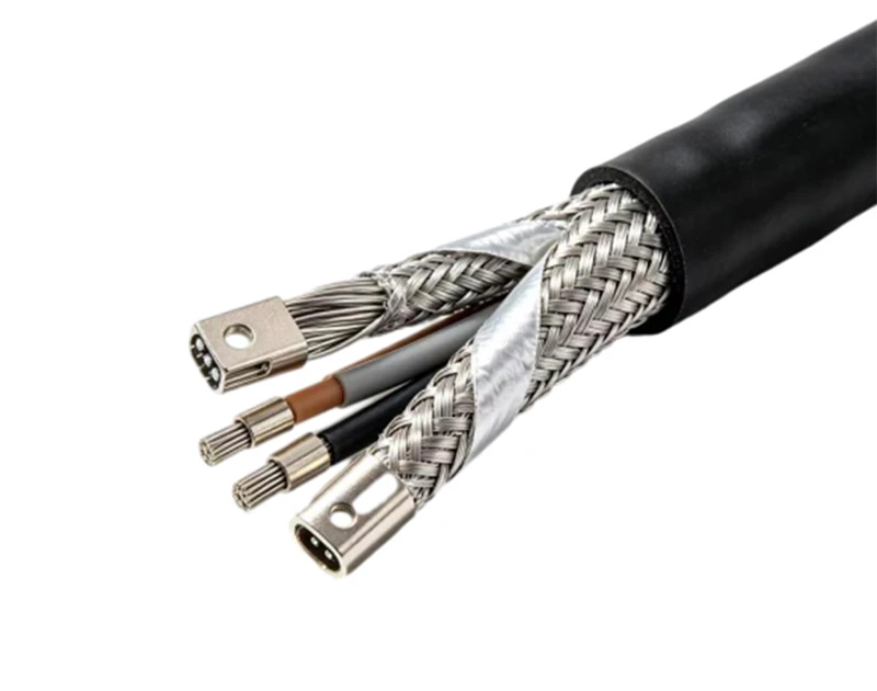
1. Define the Application Before Selecting Any Connector
Identify the equipment and installation location
The connector specification depends heavily on where the wiring harness will be installed. A connector used inside a protected dashboard has different requirements from one installed near an engine, wheel, battery, or external sensor.
Record the following application information before contacting a harness supplier:
- Vehicle, machine, device, or equipment type
- Electrical system voltage and maximum current
- Signal type, such as power, ground, analog, digital, CAN, LIN, Ethernet, or sensor signal
- Number of circuits required
- Available installation space
- Connector mating direction and access direction
- Expected mating and unmating frequency
- Exposure to water, oil, fuel, dust, chemicals, salt, mud, vibration, or abrasion
- Operating temperature and storage temperature
- Expected service life
- Applicable vehicle, industry, or customer standards
Separate power circuits from signal circuits
Power and signal circuits should not be specified in the same way. Power circuits require terminals with suitable current capacity and low contact resistance. Signal circuits may require better shielding, tighter contact reliability, or improved protection against electromagnetic interference.
- High-current circuits: battery, starter, motor, heater, pump, and actuator circuits
- Low-current circuits: sensors, switches, control inputs, and indicator signals
- Communication circuits: CAN, LIN, Ethernet, RS-485, and other data networks
- High-voltage circuits: electric vehicle battery, inverter, charger, and motor connections
Confirm the real operating conditions
A connector that works in a laboratory may fail in a vehicle. Temperature cycling, vibration, water ingress, terminal fretting, corrosion, and incorrect assembly can all reduce harness life.
Ask the engineering or end-user team to confirm:
- Minimum and maximum continuous operating temperature
- Short-term peak temperature near engines, exhaust systems, or motors
- Vibration level and frequency range
- Water exposure and required IP protection level
- Exposure to automotive fluids and cleaning chemicals
- Potential bending, pulling, or twisting of the harness
- Required flexing cycles for moving harness sections
- Required connector locking and secondary locking features
2. Select the Connector Housing and Configuration
Choose the correct connector family
The connector housing should be selected according to circuit count, electrical load, environmental conditions, installation space, and service requirements. Purchasing teams should avoid selecting a housing based only on price or visual similarity.
Common connector configurations include:
- Wire-to-wire connectors for joining two harness sections
- Wire-to-board connectors for connecting a harness to a PCB
- Wire-to-device connectors for sensors, motors, valves, and control units
- Inline connectors for serviceable harness sections
- Sealed connectors for wet or contaminated environments
- Unsealed connectors for protected interior locations
- Right-angle connectors for limited installation space
- Panel-mount connectors for fixed equipment openings
- High-voltage connectors with touch-safe protection and interlock functions
Specify the number of positions and circuits
The number of connector positions must match the electrical schematic and future service requirements. Do not specify only the currently used positions if additional circuits may be added later.
When defining the circuit count, consider:
- Count every electrical circuit in the schematic.
- Identify power, ground, communication, and signal circuits separately.
- Reserve positions only when there is a confirmed expansion requirement.
- Check whether unused cavities require sealing plugs or blanking accessories.
- Confirm whether the connector family offers the required number of positions in the same series.
Check keying and polarization
Keying prevents similar connectors from being mated incorrectly. A proper specification should define the required key position, color, coding, or mechanical polarization.
- Use different keys for connectors with similar shapes but different functions.
- Confirm that mating connectors cannot be reversed or offset.
- Use color coding only as a supplement to mechanical keying.
- Check that the keying method remains visible after installation.
- Confirm that spare connector positions do not create a cross-connection risk.
Specify locking and secondary locking features
The primary lock holds the connector halves together. The secondary lock, often called a terminal position assurance feature, ensures that each terminal is fully inserted and prevents terminal back-out.
Specify the following features:
- Primary connector latch type
- Terminal position assurance requirement
- Connector position assurance requirement when applicable
- Resistance to accidental release
- Required tool for connector release
- Visual or audible confirmation of full mating
3. Select the Correct Terminals for the Wire and Load
Match the terminal to the wire size
The terminal must match the conductor cross-sectional area and insulation diameter. A terminal that is too small may create high resistance and overheating. A terminal that is too large may produce a weak crimp and poor mechanical retention.
Specify wire size using a recognized unit, such as square millimeters or AWG. The RFQ should include:
- Conductor size range
- Conductor material, normally copper or tinned copper
- Insulation outside diameter
- Stranded or solid conductor construction
- Required insulation support range
- Approved wire types and insulation materials
Match the terminal to the current and voltage
Current ratings are affected by wire size, ambient temperature, terminal material, connector spacing, number of loaded circuits, and allowable temperature rise. Do not rely only on a catalog current value without checking the actual application conditions.
Confirm:
- Continuous current rating
- Peak or inrush current
- Operating voltage
- Dielectric withstand voltage
- Contact resistance
- Maximum allowable temperature rise
- Derating requirements when multiple circuits are loaded
Choose the correct terminal plating and material
Terminal material and plating affect corrosion resistance, electrical stability, insertion force, and cost. Tin-plated terminals are common for many automotive applications. Gold-plated terminals may be considered for low-level signals or demanding environments, while other plating systems may be used for specific high-current or high-temperature applications.
The specification should identify:
- Base terminal material
- Plating type
- Plating thickness when controlled by the customer standard
- Contact area plating requirement
- Crimp barrel material
- Corrosion resistance requirement
- Compatibility with the mating terminal
Specify seals and cavity protection
For sealed connectors, the terminal, wire insulation, cavity seal, and connector housing must work together. A sealed housing alone does not guarantee water resistance.
Define:
- Individual wire seal or interface seal requirement
- Seal material
- Seal color and wire size range
- Unused cavity sealing plug requirement
- Required IP rating or customer sealing standard
- Resistance to water, oil, fuel, and cleaning agents
4. Follow a Step-by-Step Connector and Terminal Specification Process
First step: Create the circuit list
Start with a complete circuit list rather than a connector catalog. Each circuit should have a unique identification number and a clearly defined electrical purpose.
Include these fields:
- Circuit number
- Source component
- Destination component
- Power, ground, signal, or communication function
- Wire size
- Wire color
- Fuse or protection device
- Maximum continuous current
- Peak current where applicable
- Required shielding or twisting
Second step: Define the connector interface
For every connection point, define whether the connector is wire-to-wire, wire-to-device, wire-to-board, or panel mounted. Identify the mating half, mounting method, and installation direction.
Record:
- Connector reference number
- Housing part number or required connector series
- Plug or receptacle type
- Number of positions
- Keying and polarization
- Mating component
- Mounting clip, bracket, or bolt requirement
- Primary and secondary locking requirements
Third step: Select the terminal and seal
Choose the terminal based on wire size, insulation diameter, current, voltage, plating, and environmental requirements. Then select the correct seal, cavity plug, and locking accessories.
Verify that:
- The terminal is approved for the selected housing.
- The terminal accepts the specified conductor size.
- The terminal insulation support matches the wire diameter.
- The terminal is compatible with the mating terminal.
- The seal fits both the terminal and the wire insulation.
- The crimp tooling is available for the terminal.
Fourth step: Check the physical envelope
Use a mechanical drawing or three-dimensional model to confirm that the connector fits the available space. Check latch access, bend radius, cable exit direction, and service clearance.
Review:
- Overall connector length, width, and height
- Terminal cavity orientation
- Wire exit direction
- Minimum wire bend radius
- Clearance for mating and unmating
- Clearance for service tools
- Mounting clip and bracket position
- Risk of contact with sharp edges, heat sources, or moving parts
Fifth step: Confirm environmental performance
Compare the connector and terminal data with the actual installation conditions. Request test reports or manufacturer data when the application is safety-critical or exposed to harsh conditions.
Check:
- Temperature rating
- Vibration and mechanical shock rating
- Water and dust protection
- Salt spray and corrosion resistance
- Fluid compatibility
- UV resistance for exposed harnesses
- Flammability rating
- High-voltage touch protection where applicable
Sixth step: Confirm crimp and assembly requirements
A suitable connector can still fail if the terminal is poorly crimped. The purchasing specification should include crimp requirements and verification methods, especially when the harness will be manufactured in large quantities.
Define:
- Approved crimp applicator or tooling
- Conductor crimp height and width
- Insulation crimp height and width
- Crimp pull-out force
- Required wire brush length
- Acceptable bellmouth and cutoff tab length
- Terminal insertion force
- Terminal retention force
- Crimp cross-section inspection frequency
Seventh step: Build and review the connector BOM
Create a connector bill of materials that separates the housing, terminals, seals, cavity plugs, backshells, clips, and other accessories. This prevents missing components during quotation and production.
A useful connector BOM should include:
- Item number
- Component description
- Manufacturer name
- Manufacturer part number
- Approved alternate part number
- Quantity per harness
- Required annual quantity
- Packaging requirement
- Target price or cost category
- Lead time
- End-of-life or obsolescence status
Eighth step: Validate the sample harness
Do not approve a connector only from a drawing or quotation. Build and test a representative sample harness using the proposed connector, terminal, wire, seal, and assembly method.
Sample validation should include:
- Visual inspection of the connector and terminal assembly.
- Terminal retention and pull-out testing.
- Continuity and pin-to-pin verification.
- Insulation resistance testing.
- Contact resistance measurement.
- High-potential testing when required.
- Water ingress testing for sealed connectors.
- Vibration and temperature cycling when required.
- Trial installation on the actual vehicle or equipment.
- Review and approval of the final drawing and BOM.
5. Prepare the Required Tools and Documents
Tools for connector specification and design review
The purchasing and engineering teams need accurate tools to prevent interface errors and incomplete RFQs.
- Electrical schematic or circuit diagram
- Connector pinout drawing
- Wire harness drawing
- Three-dimensional connector model or dimensional drawing
- Digital caliper or measurement gauge
- Wire size and insulation diameter chart
- Terminal and seal compatibility chart
- Current and voltage calculation worksheet
- Connector BOM template
- Supplier technical datasheets
- Applicable customer or industry standards
Tools for terminal crimping and inspection
Production and sample approval require the correct tooling for the selected terminal. Generic pliers or unapproved crimp tools can create hidden defects.
- Approved hand crimp tool for prototype work
- Production crimp applicator or automated crimp machine
- Wire stripper
- Terminal insertion and extraction tools
- Crimp height micrometer or dedicated crimp gauge
- Crimp pull tester
- Digital multimeter
- Micro-ohmmeter for low contact resistance testing
- Insulation resistance tester
- High-potential tester when required
- Crimp cross-section inspection equipment
- Magnifying lamp or inspection microscope
Documents to send with a purchasing RFQ
A supplier can provide a more accurate quotation when the request includes technical information instead of only a connector photo or a short description.
Include:
- Wiring schematic
- Connector pinout table
- Wire list
- Harness drawing
- Connector and terminal BOM
- Environmental requirements
- Annual volume and forecast
- Prototype quantity
- Target production date
- Required quality certificates
- Packaging and labeling requirements
- Testing and inspection requirements
- Approved supplier or brand list, if applicable
6. Solve the Main Purchasing Pain Points
Pain point: The quotation is incomplete or difficult to compare
Different suppliers may quote different levels of scope. One supplier may include housings and terminals, while another may exclude seals, cavity plugs, tooling, or testing.
Request a line-by-line quotation that separates:
- Connector housings
- Terminals
- Wire seals
- Cavity plugs
- Backshells and strain reliefs
- Mounting clips and brackets
- Crimp tooling
- Assembly labor
- Testing
- Packaging
- Tooling charges
- Prototype and production pricing
Pain point: The supplier proposes an incompatible substitute
A substitute connector may look similar but have a different terminal system, keying design, current rating, seal size, or mating interface. Require the supplier to provide a formal deviation list for every alternative component.
For each proposed substitute, compare:
- Mechanical mating compatibility
- Electrical rating
- Terminal and wire compatibility
- Sealing performance
- Temperature and vibration performance
- Availability and lifecycle status
- Tooling requirements
- Impact on the existing harness drawing
Pain point: Lead time and supply continuity are uncertain
Connector shortages can stop harness production even when wire and labor are available. Purchasing teams should confirm supply continuity before approving a connector series.
Ask the supplier to provide:
- Current stock status
- Standard production lead time
- Minimum order quantity
- Packaging quantity
- Authorized distribution source
- Expected annual capacity
- End-of-life notification policy
- Approved second-source options
Pain point: The total cost is higher than the unit price
The lowest connector unit price may not result in the lowest total cost. A connector requiring manual assembly, special tooling, additional seals, or complex testing can increase the final harness cost.
Evaluate total cost based on:
- Component price
- Assembly time
- Crimp tooling investment
- Inspection and testing cost
- Scrap and rework risk
- Shipping and packaging
- Inventory carrying cost
- Potential field failure cost
Pain point: Quality responsibility is unclear
The RFQ should clearly state who is responsible for connector authenticity, incoming inspection, crimp quality, electrical testing, and change control.
Define:
- Required incoming inspection records
- Material and plating certificates
- Crimp inspection standards
- Electrical test coverage
- Traceability requirements
- Nonconformance handling process
- Engineering change notification requirements
- Corrective action response time
7. Avoid Common Connector and Terminal Specification Mistakes
Mistake: Selecting by appearance only
Two connectors may have similar shapes but different terminal arrangements, keying, voltage ratings, sealing systems, or mating interfaces. Always verify the exact manufacturer part number and technical drawing.
Mistake: Ignoring the wire insulation diameter
A terminal may accept the conductor size but not the insulation diameter. This can cause a loose insulation crimp, damaged seal, poor strain relief, or water leakage.
Mistake: Using a terminal outside its approved housing
Terminals are designed for specific connector cavities. Using a visually similar terminal can result in incorrect retention, poor contact pressure, or terminal back-out.
Mistake: Rating the connector only by peak current
Continuous current, ambient temperature, adjacent loaded circuits, and allowable temperature rise must be considered. A connector that survives a short peak may still overheat during continuous operation.
Mistake: Omitting unused cavity plugs
Unused cavities in sealed connectors normally require the correct cavity plugs. Leaving them open can compromise water and dust protection.
Mistake: Forgetting mating connector requirements
Every connector needs a compatible mating half. Confirm whether the mating connector is supplied by the harness manufacturer, the equipment manufacturer, or another supplier.
Mistake: Using unapproved crimp tooling
Improper tooling can damage the terminal, cut conductor strands, create an incomplete crimp, or produce excessive contact resistance. Use the terminal manufacturer's approved tooling whenever possible.
Mistake: Failing to control engineering changes
Connector suppliers may change materials, plating, tooling, or production locations. Require written approval before any change that affects form, fit, function, reliability, or regulatory compliance.
Mistake: Comparing suppliers only by price
Price should be evaluated together with quality records, component authenticity, technical support, lead time, testing capability, and long-term supply stability.
8. Use a Final Connector Specification Checklist
Electrical checklist
- Is the voltage rating suitable for the application?
- Is the continuous and peak current clearly defined?
- Is derating considered for temperature and circuit loading?
- Are power, ground, signal, and communication circuits identified?
- Are contact resistance and insulation resistance requirements defined?
Mechanical checklist
- Does the connector fit the available installation space?
- Are the plug and receptacle mating correctly?
- Is the keying or polarization correct?
- Are primary and secondary locks included?
- Is there enough clearance for assembly and service?
- Is the wire bend radius acceptable?
Environmental checklist
- Is the temperature range suitable?
- Is the required sealing or IP rating defined?
- Are fluid, chemical, salt spray, and corrosion requirements covered?
- Is the connector suitable for vibration and shock?
- Are cavity plugs and wire seals included?
Manufacturing checklist
- Is the terminal compatible with the selected wire?
- Is the correct crimp tooling available?
- Are crimp height and pull-force requirements defined?
- Are terminal insertion and retention requirements defined?
- Can the supplier perform continuity and electrical testing?
- Are production samples required before approval?
Purchasing checklist
- Does the BOM include every housing, terminal, seal, and accessory?
- Are manufacturer part numbers listed?
- Are approved alternates clearly identified?
- Are lead time, MOQ, and annual volume confirmed?
- Are packaging and labeling requirements included?
- Is the change control process documented?
- Is total cost evaluated instead of unit price alone?
Conclusion: Build a Complete and Verifiable Connector Specification
Specifying connectors and terminals for a custom wiring harness requires more than selecting a housing from a catalog. The correct process begins with the application, separates power and signal requirements, matches terminals to wire size and current, confirms mechanical and environmental performance, and validates the complete assembly through samples and testing.
A complete RFQ should include the circuit list, connector pinout, wire specifications, connector BOM, environmental conditions, crimp requirements, testing standards, annual volume, and supply continuity expectations. This information allows a Custom Automotive Wiring Harness Manufacturer to quote accurately and prevents costly changes during production.
Onlink supports custom automotive wiring harness development with connector selection, terminal crimping, prototype assembly, electrical testing, and production supply coordination. When you need a reliable Custom Automotive Wiring Harness Manufacturer, provide the complete technical requirements and request a verified harness solution from Onlink.


